PiCON Build Guide 1/3 – Getting Started
Added by iCON on March 12, 2024iCON
Say thanks by giving iCON a tip! Why?
If you are using a Pro Micro, create a solder bridge across jumper J1 to allow proper operation of the rumble motor. Even if you are not installing a rumble motor at this time, it will be much easier to solder J1 before installing the Pro Micro in your light gun. If solder is sticking to your soldering iron tip and not the solder pads when you lift the tip off, feed more solder into the puddle. Be careful not to keep the heat on the solder pads too long to prevent them from delaminating from the PC board. Most/all other ATmega32u4 based microcontroller boards do not have a jumper that needs to be bridged, only the Pro Micro.
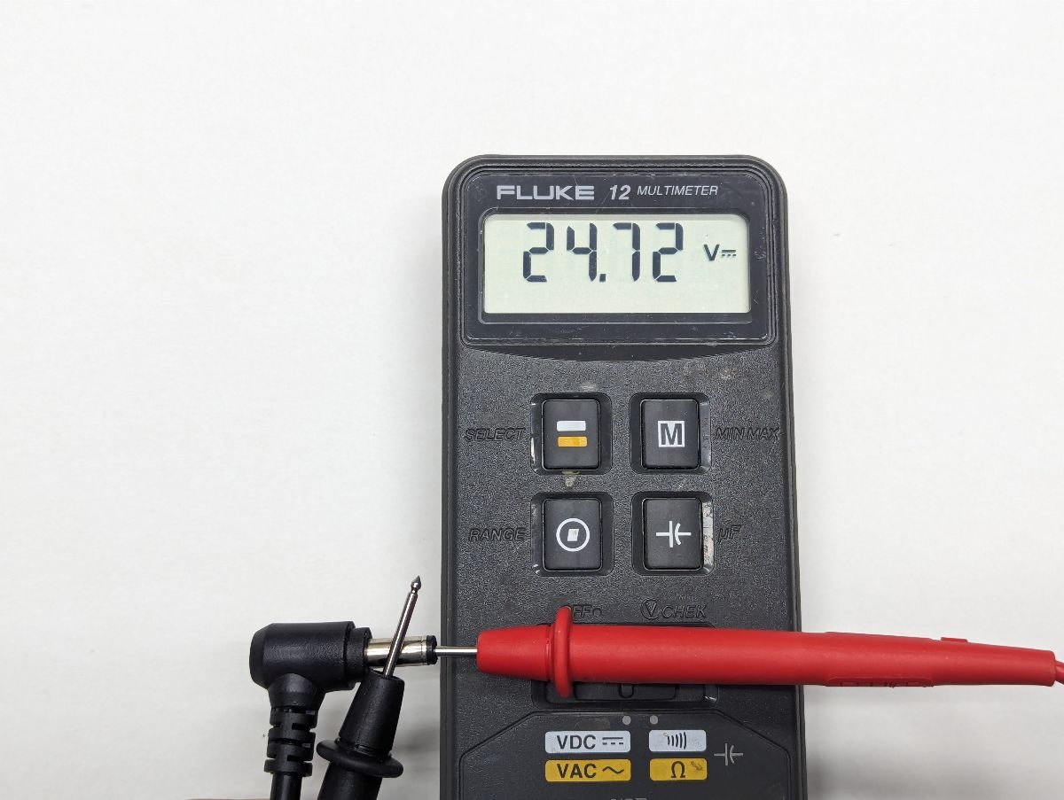
Plug your solenoid power supply into mains and use a voltmeter to verify that the center pin of the barrel connector is positive and that the voltage reading is what you expect. If you do not have a voltmeter, borrow one or buy one. You do not need an expensive voltmeter. Disconnect your power supply from mains.
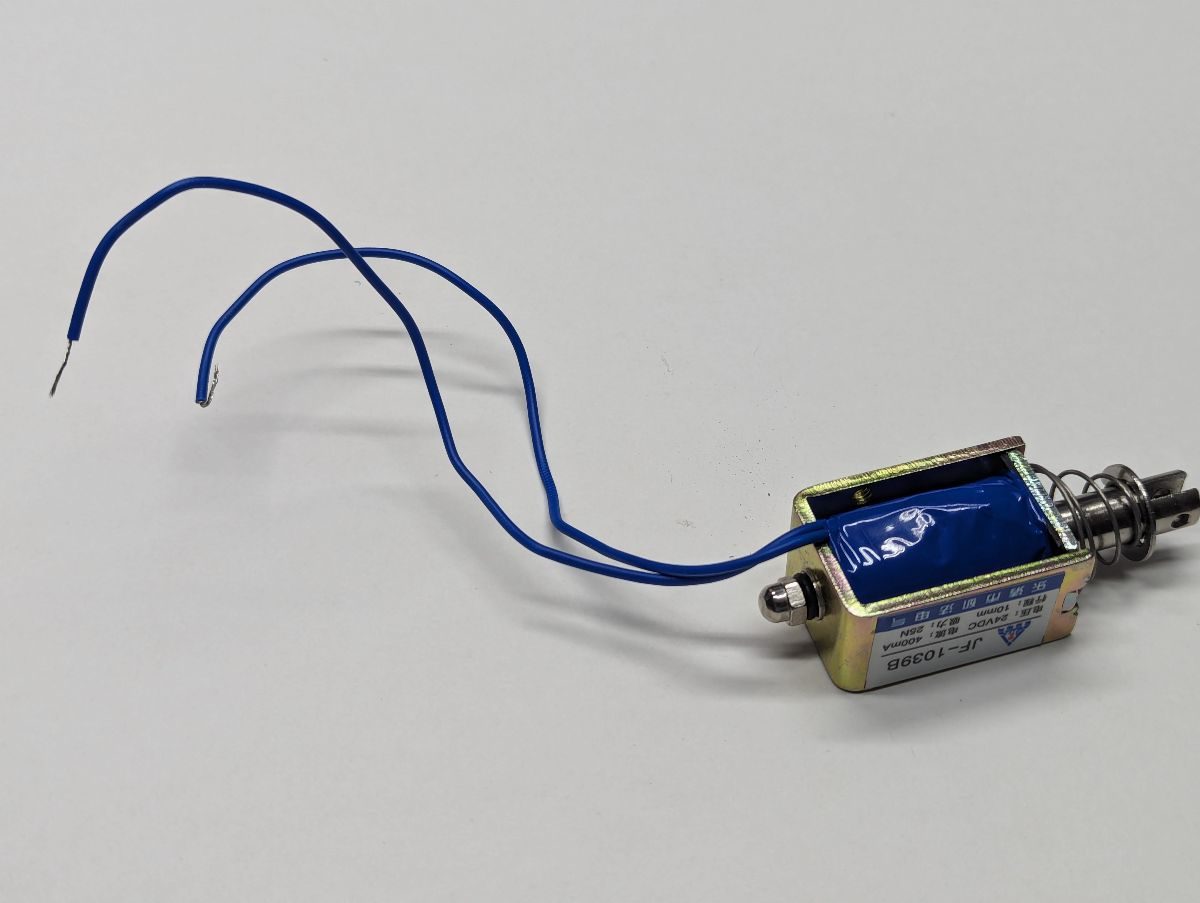
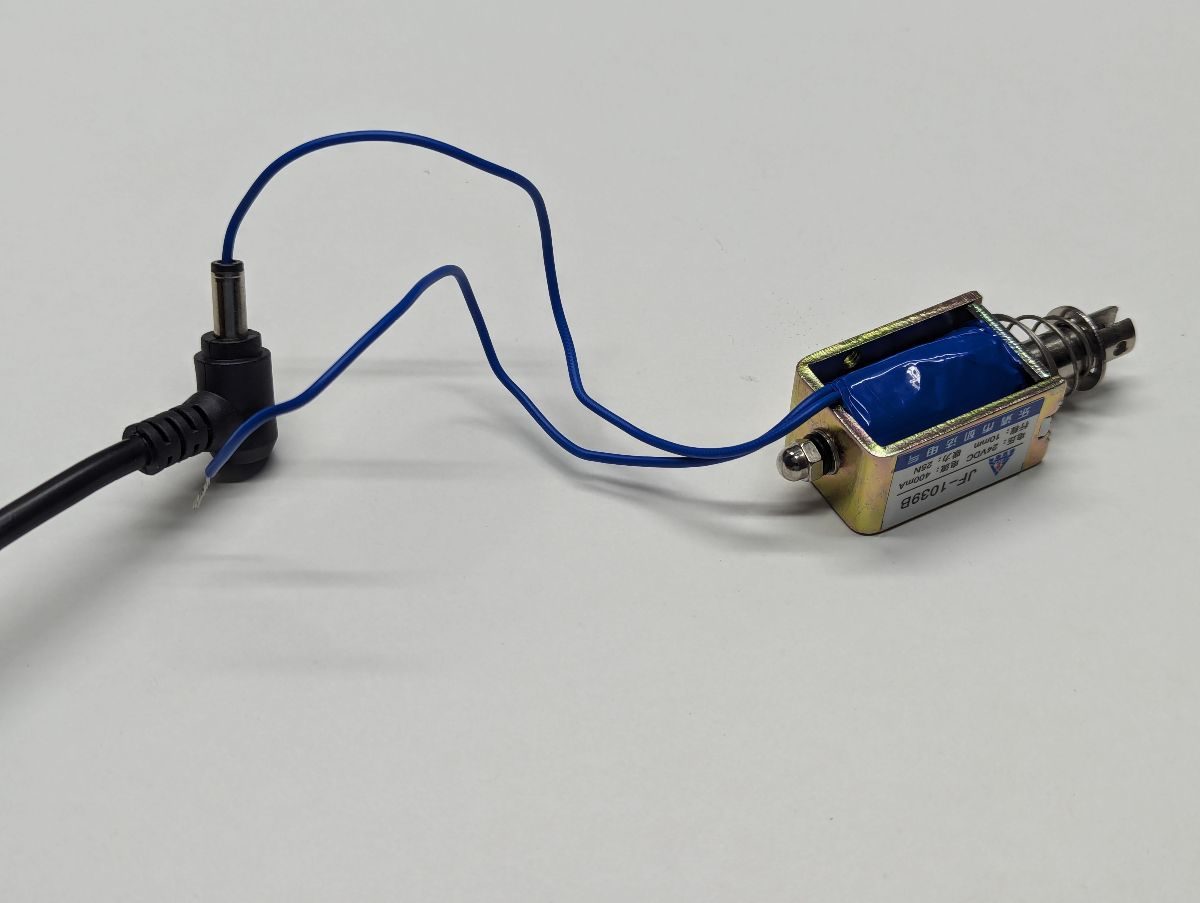
Test the solenoid and the power supply that you intend to use as part of your build. If your solenoid does not have a back pin that keeps the shaft from falling out, put something heavy in front of the solenoid so the plunger does not fly out during this test. Strip a short amount of insulation from the ends of your solenoid if they are not stripped already. Fold the exposed conductor of one of the solenoid wires back over its insulation and push this wire into the center of your power supply barrel connector. Make sure none of the exposed wires are touching the outer conductor of the barrel connector. Plug the power supply to mains. Momentarily touch the other exposed solenoid wire to the outer shell of the barrel connector. This should actuate the solenoid. You will also likely see a small spark, this is normal. Do this a few times to make sure the solenoid pull in is strong and reliable. If the solenoid does not actuate, use an ohmmeter across the solenoid wires – you should measure a very low resistance. If you read infinite resistance, your solenoid coil is damaged. If the solenoid resistance measures properly, you most likely need a different, more powerful power supply. Disconnect the power supply from mains and remove the wire that was previously inserted in the barrel connector.
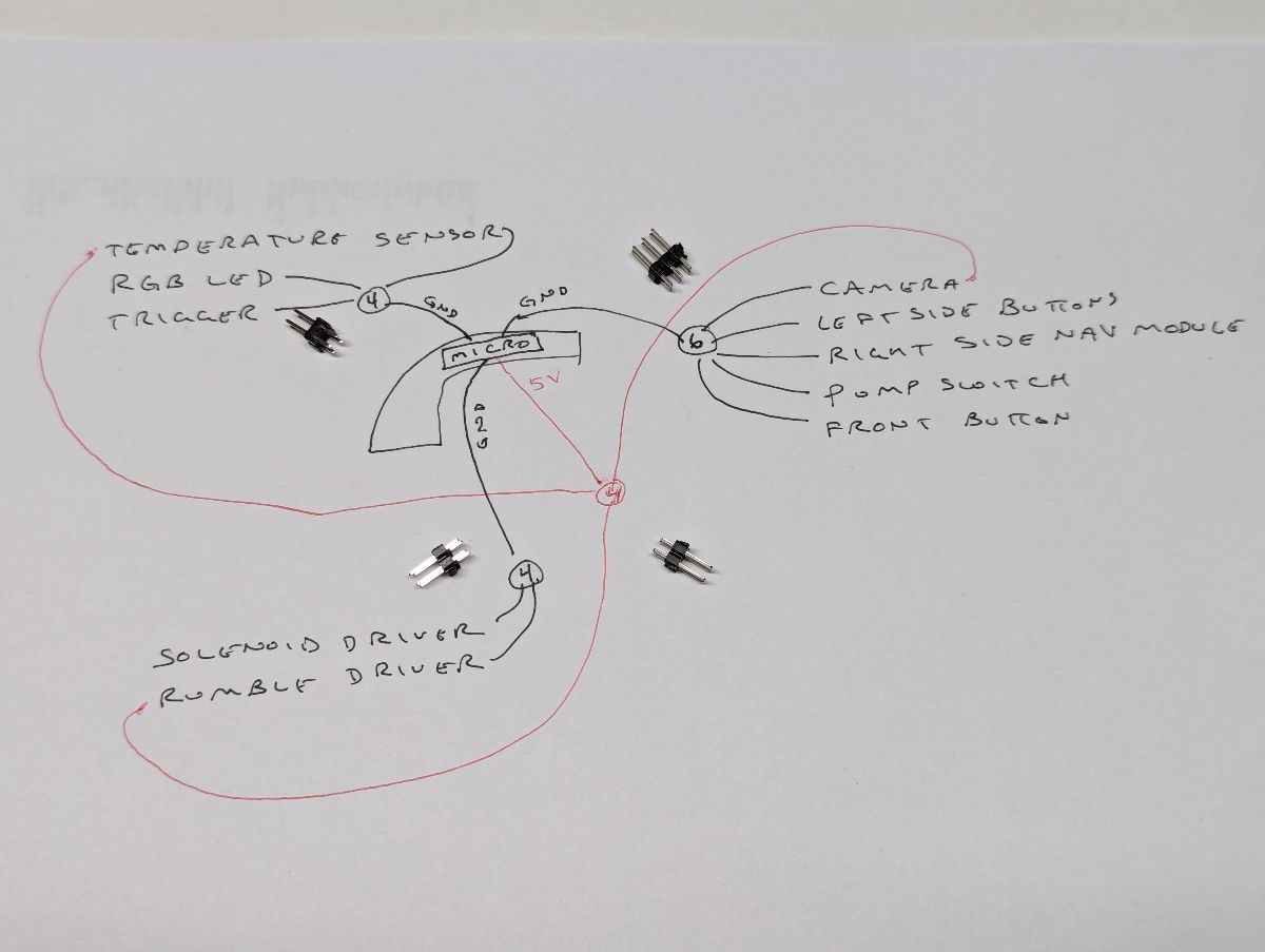
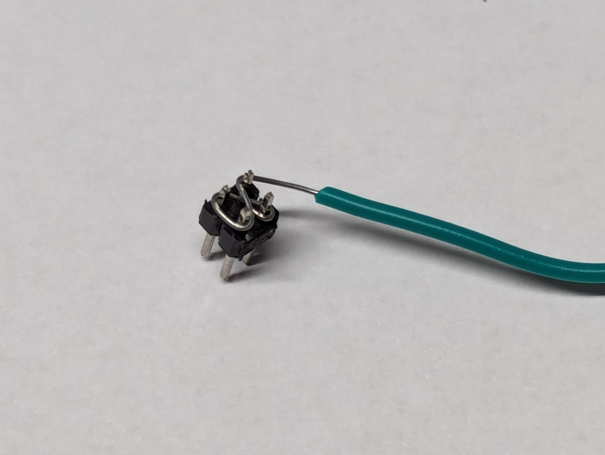
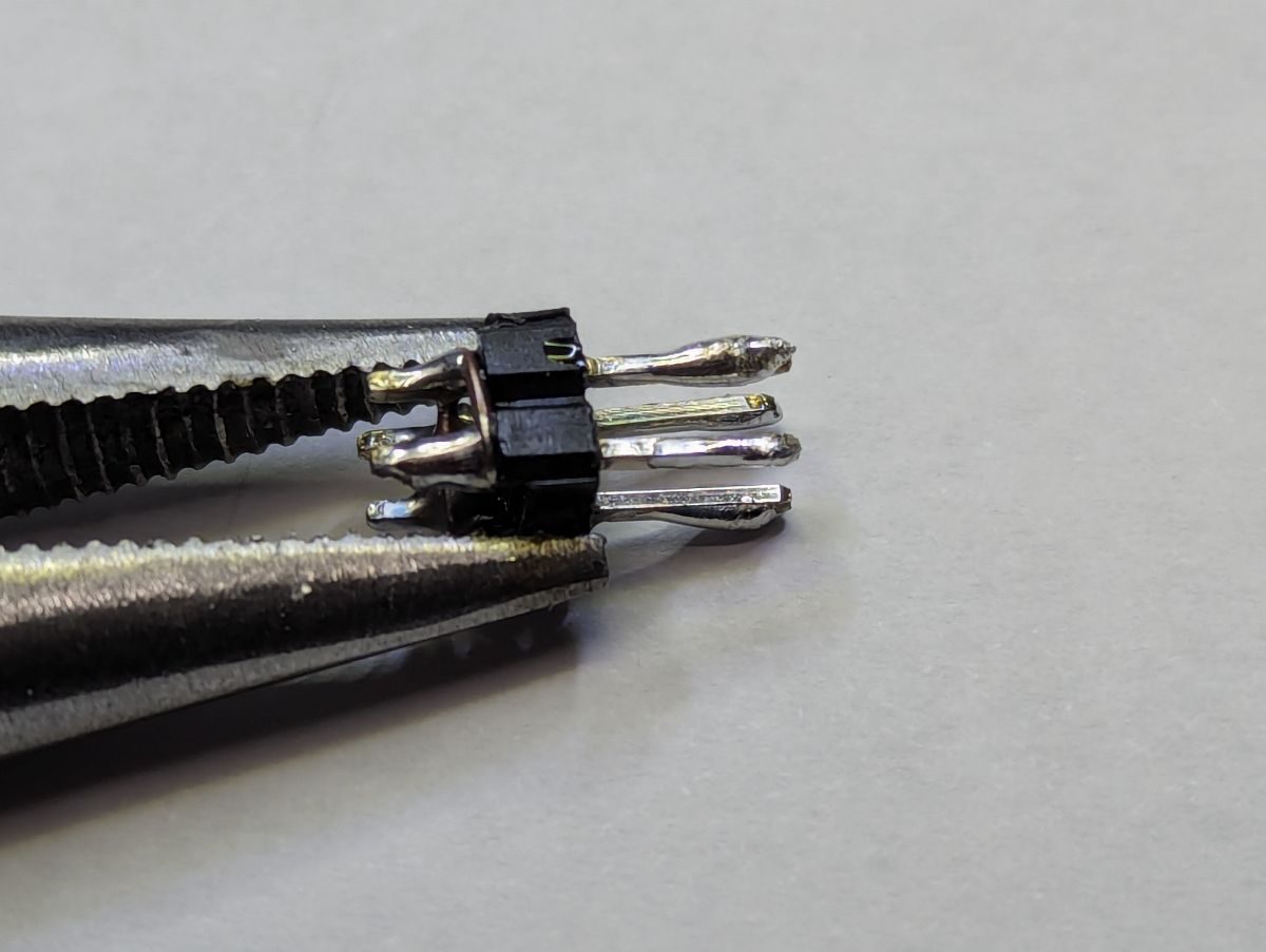
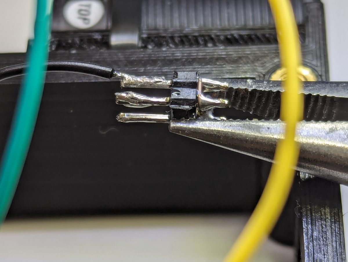
Most microcontroller boards will not have enough pins to allow for all of the ground/5v/3.3v connections that you will need to make. You need to plan your connections before you start to solder wires to the microcontroller so you don’t run out of pins. A simple and compact way of distributing these pins to multiple connections in your lightgun is to use a dual-row Dupont pin header. On the short pin side of the dual-row pin header, weave a solid core wire in and out of the pins then solder all of the points where the pin and wire cross. Tin the long pins to make it easier to solder wires to the long pins. To prevent any short circuits, wrap the completed distribution block in shrink wrap tubing.
While it may not seem important while you are building your lightgun, using a variety of wire colors will make troubleshooting and repairing your lightgun easier. Create a wiring diagram for your build and keep a record of what color was used for each connection. It is highly recommended that black wire only be used for ground connections and red wire only be used for Vcc (5v or 3.3v) connections. If you are using a Pico microcontroller, use red for 5v and orange for 3.3v. Do not use black or red (or orange) for any other connection. 28 gauge stranded & tinned silicone wire is highly recommended for almost all internal connections. The thin size of the 28 gauge wire will make packing all of those wires inside the lightgun easier. Silicone wire does not melt back when soldering. Stripping silicone wire can be done by pinching and pulling the insulation from the end of the wire (fingernails required). The only wires that should be a heavier gauge are the two wires that connect your GX connector to the solenoid driver PCB where 22 gauge wire is recommended.