PiCON Build Guide 2/3 – Postprocessing & Heat Set Inserts
Added by iCON on March 11, 2024iCON
Say thanks by giving iCON a tip! Why?
Gently press the two halves of the Trigger Guard together. Do not force them together, they should fit together with very little effort. If they don’t, file or sand any areas or z-seams that preventing the parts from fitting properly, pay close attention to any z-seams on the pins that align the parts. The two halves should fit together without any gap between them.
Test fit the Trigger Guard Pins in the square holes in the Trigger Guard. Do not force the pins in the hole. If they do not slide in easily, sand or file any z-seam bumps on the Trigger Guard Pins and file any areas of the square holes that may be preventing the pins from being inserted.
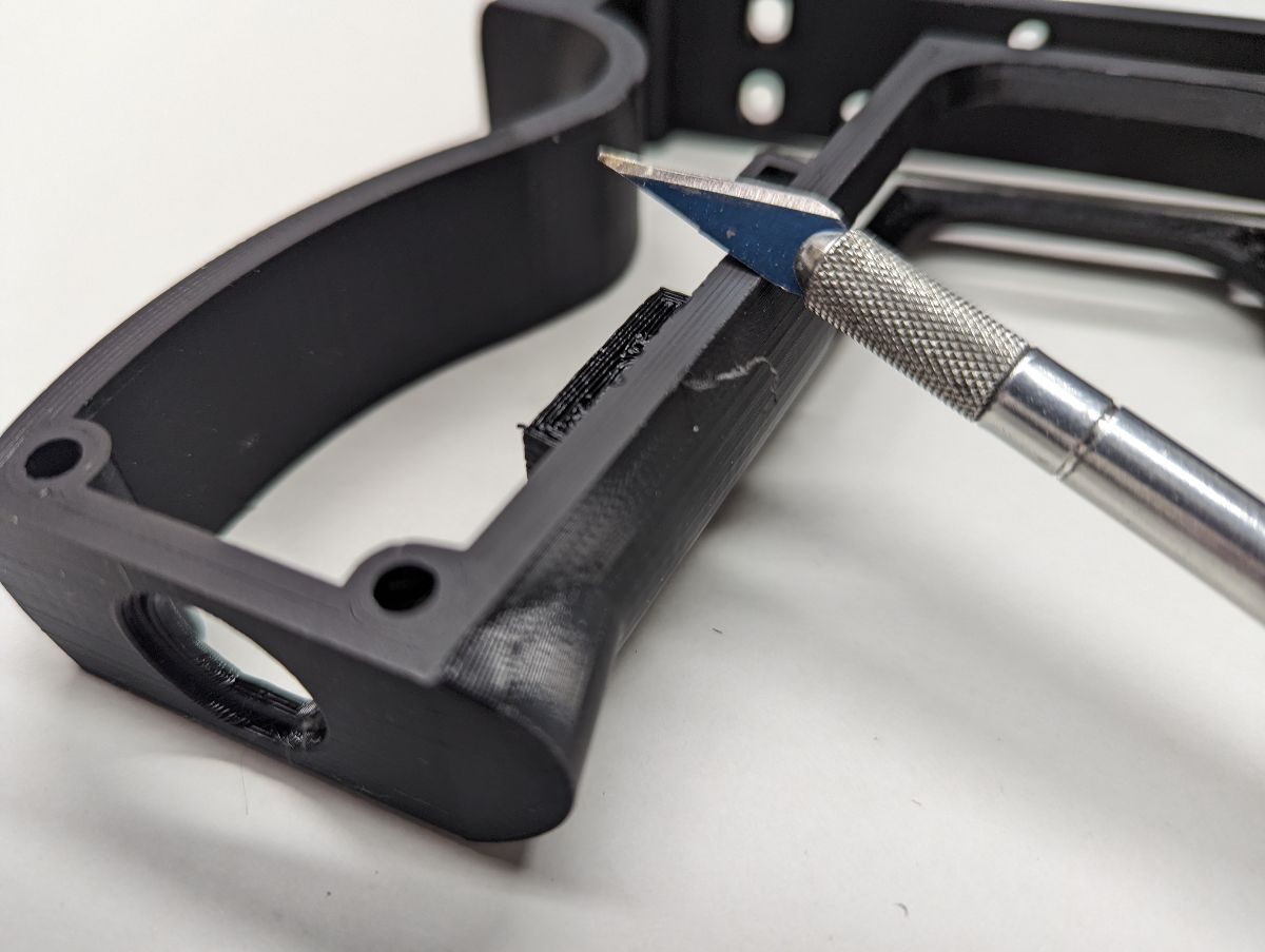
If your first layer of filament tends to squeeze beyond where it should, sand/file/scrape it off. If left as-is, it will be particularly annoying on the grip. The non-sharp edge of an X-ACTO knife blade can be used as a scraper – use a light touch and work in small sections and the filament “lip” should peel off in threads. You may want to ease the edge of the top layer too to make the grip more comfortable. Test fit the Trigger Guard pins in the square holes in the Frame. If necessary, use a file or Xacto knife to clean up the square holes in the Frame. Test fit the assembled Trigger Guard in the Frame. It should slide in without much effort. If there is any resistance, most likely your overhang needs to be filed/sanded smooth. If you are using a GX connector on your build, test the fit of the GX male connector in the butt of the lightgun.
Printing the sides vertically sometimes causes holes to be more oval than round. Use a 3mm (or 1/8”) drill bit to make the screw holes in the sides round. M3 screws should fit in these holes without any binding. If you are using 12x12mm pushbuttons in your side panels, make sure that the button cap moves in and out of the holes without any binding. Use an Xacto knife, round file or sandpaper to clean up any filament that is causing the button cap to bind.
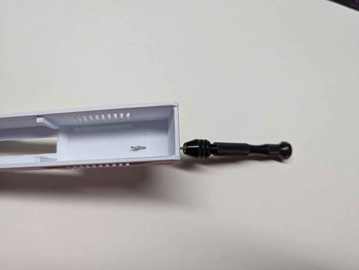
Use a 3mm (or 1/8”) drill bit to make the screw holes in the side of the Slide round. M3 screws should fit in these holes without any binding. If you would like to insert a different color filament in the gun sight holes, use a 1.8mm drill bit to make those holes round. Be sure to drill all the way through to the inside of the Slide to allow removing filament from the gun sight holes easier. Note that the PiCON only supports NeoPixel LEDs for illuminating the gun sights. Driving NeoPixel LEDs in only supported when using OpenFIRE firmware. There are two temporary walls on the inside of the slide. Break those walls out. It may be necessary to file or sand any remaining filament from the sides.
To assure smooth movement of the Pump, all support material must be removed and smooth. Insert the Pump Mount into the slot on the Pump and slide it back and forth. If there are any restrictions in movement, carefully inspect the Pump to verify that all support material has been removed and that all surfaces are smooth. File or sand as needed. Use the tip of an Xacto knife to open the two small holes in the spring channel to make it easier to insert the M2 screws.
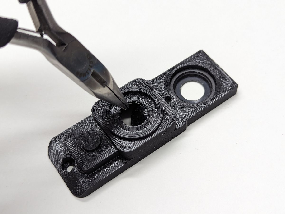
If you are going to install a 12x12mm pushbutton or an analog joystick module in the front of the lightgun, knockout the center circle and clean up the hole so the pushbutton cap slides easily in and out. If you are installing a 12x12mm pushbutton, insert the Front Button Spacer and verify that it fits flush. If needed, use a flat head screwdriver to scrape away any bumps or left over support material from the pushbutton cavity.
Install a M3x5(OD)x6(L) heat set insert in the hole closest to the bottom front of the frame. This hole passes all the way through the frame so you may want to use something on the inside of the frame to keep from pressing the heat set insert too far in. Install another M3x5(OD)x6(L) heat set insert in the hole closest to the trigger guard in the bottom front of the frame. These 2 heat set inserts are used to hold the pump mount to the frame.
Install (2) M2x3.5(OD)x4(L) heat set inserts in the rectangular cavity at the bottom front of the frame to hold the pump switch to the frame. If you don’t have M2 heat set inserts, you can use longer M2 screws and washers and nuts to hold the pump switch to the frame.
The two remaining holes are used to mount the accelerometer/gyroscope which is only supported by the OpenFIRE firmware.
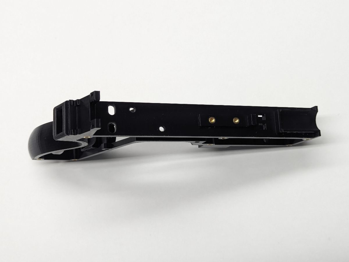
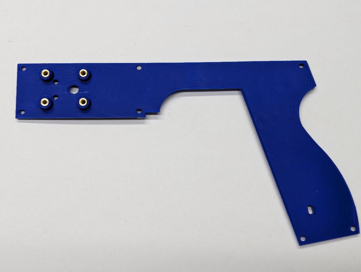
If you are using a 40mm bearing rail, install (2) M3x5(OD)x6(L) heat set inserts in the top center of the Frame. If you are using a 55mm bearing rail, install (3) M3x5(OD)x6(L) heat set inserts in the top center of the Frame. There are separate Frames for 40mm and 55mm bearing rails. If you want to install the solenoid noise dampener, install (2) M2x3.5(OD)x4(L) heat set inserts in the top center of the Frame (note that the noise dampener holes were added in rev. 2 of the Frame).
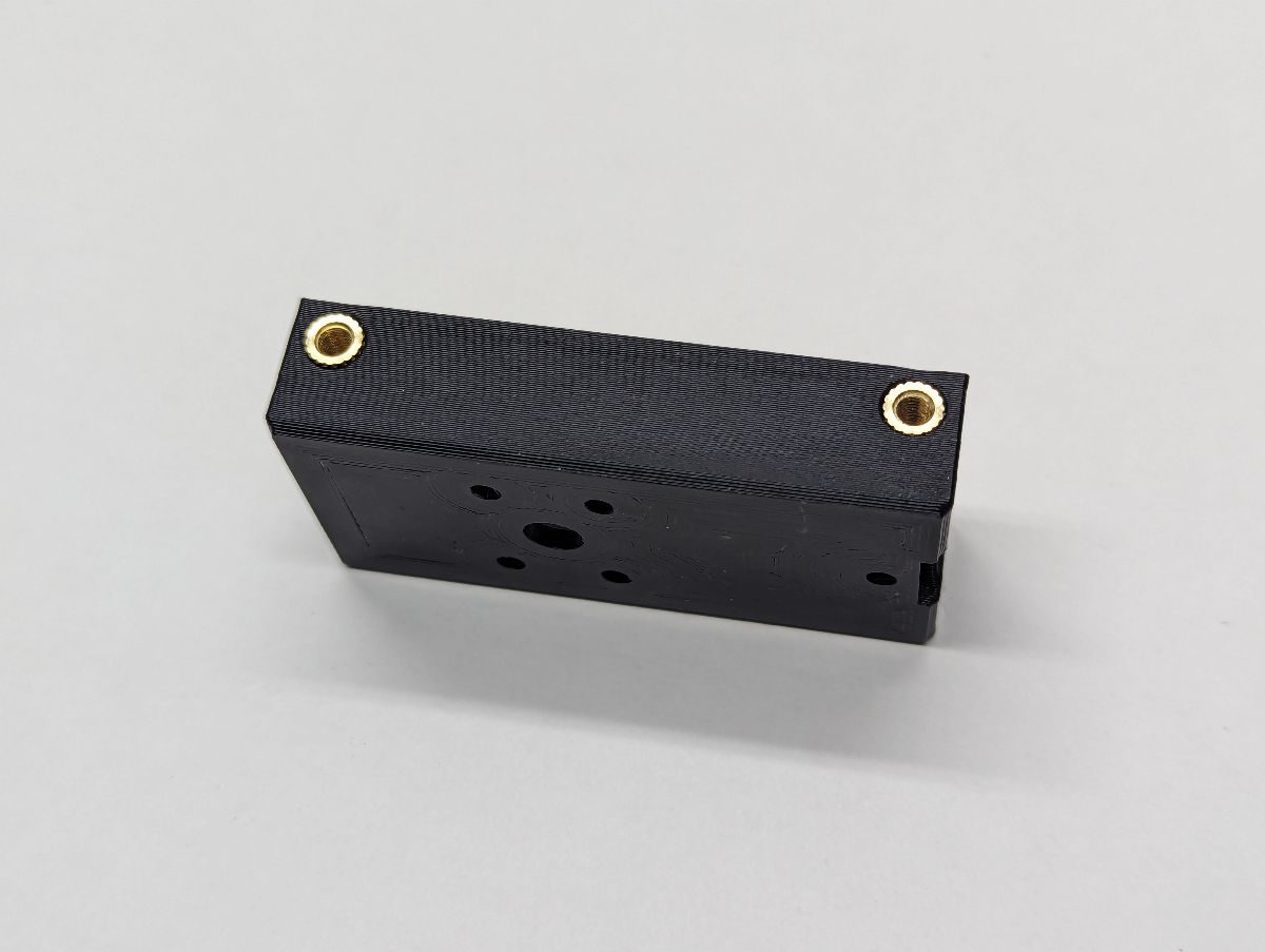
Install (4) M3x5(OD)x6(L) heat set inserts in the sides of the bearing-solenoid mount. These are used to hold the slide to the bearing-solenoid mount.
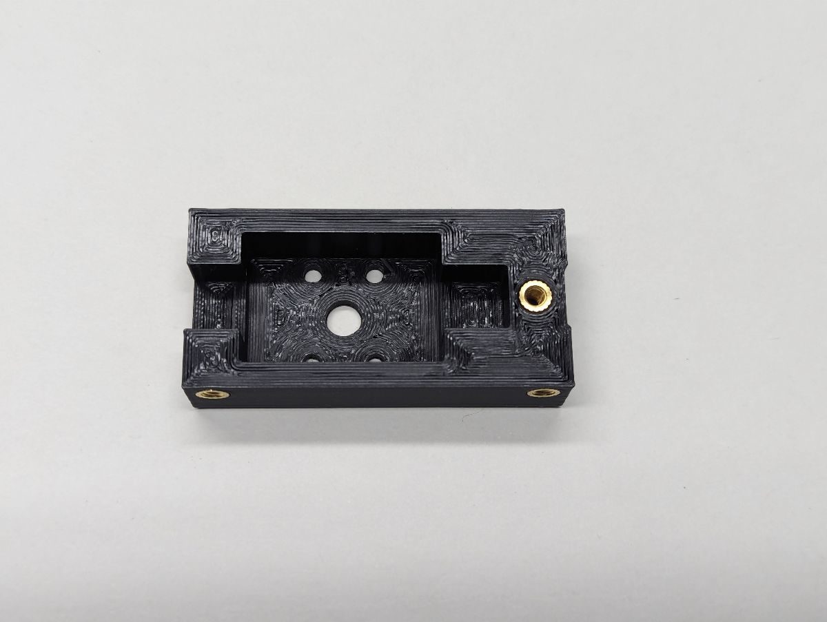
Install (1) M3x5(OD)x6(L) heat set insert in the underside of the bearing-solenoid mount. This is used to hold the shaft of the solenoid to the bearing-solenoid mount.
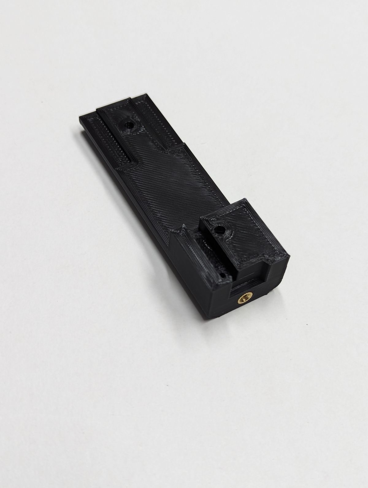
Install (1) M3x5(OD)x6(L) heat set insert in the front of the Pump Mount. Do not install heat set inserts in the holes in the bottom of the Pump Mount, these holes are used to recess the heads of the screws used to fasten the Pump Mount to the Frame.