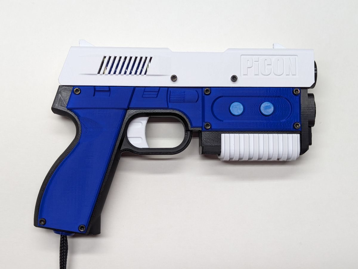
PiCON Build Guide 3/3 – Assembly
Added by iCON on February 2, 2024iCON
Say thanks by giving iCON a tip! Why?
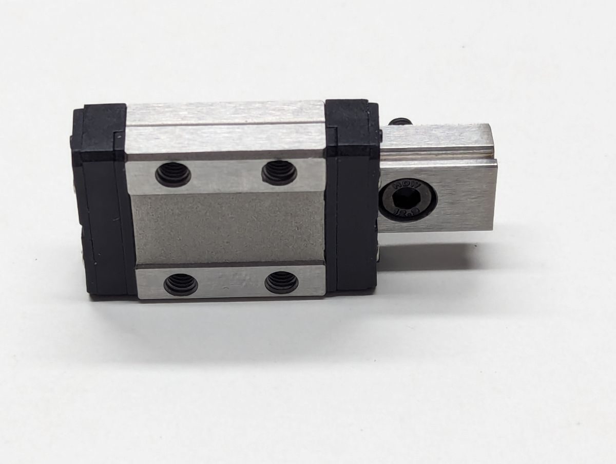
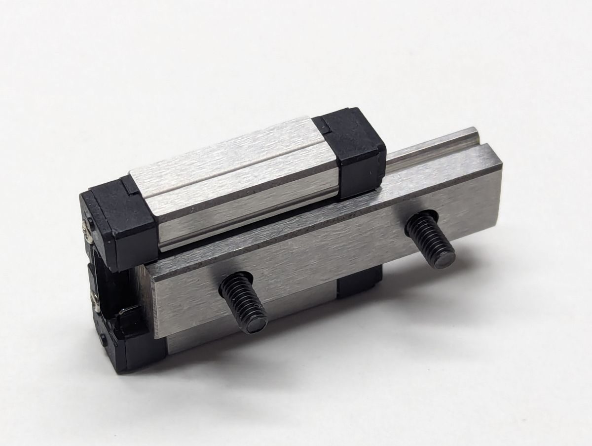
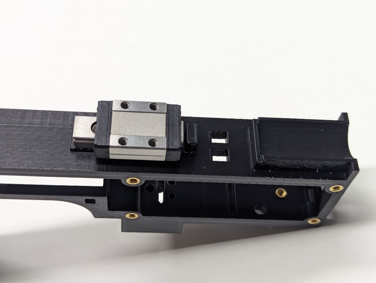
To prevent bearings from falling out, do not remove the rail from the bearing block for this step. Carefully slide the bearing block past one end of the rail just far enough to drop an M3x8 screw in the rail. Slide the bearing block the other way just far enough to drop another M3x8 screw in the other rail cavity. If you are using a 40mm rail, there will be two screws used to hold the rail to the Frame. If you are using a 55mm rail, there will be 3 screws. Secure the screws to the Frame.
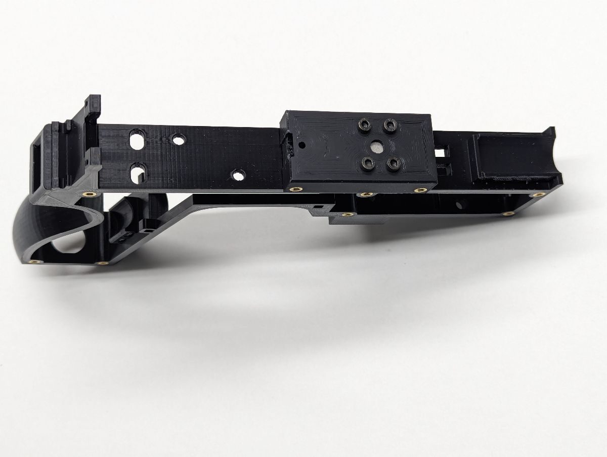
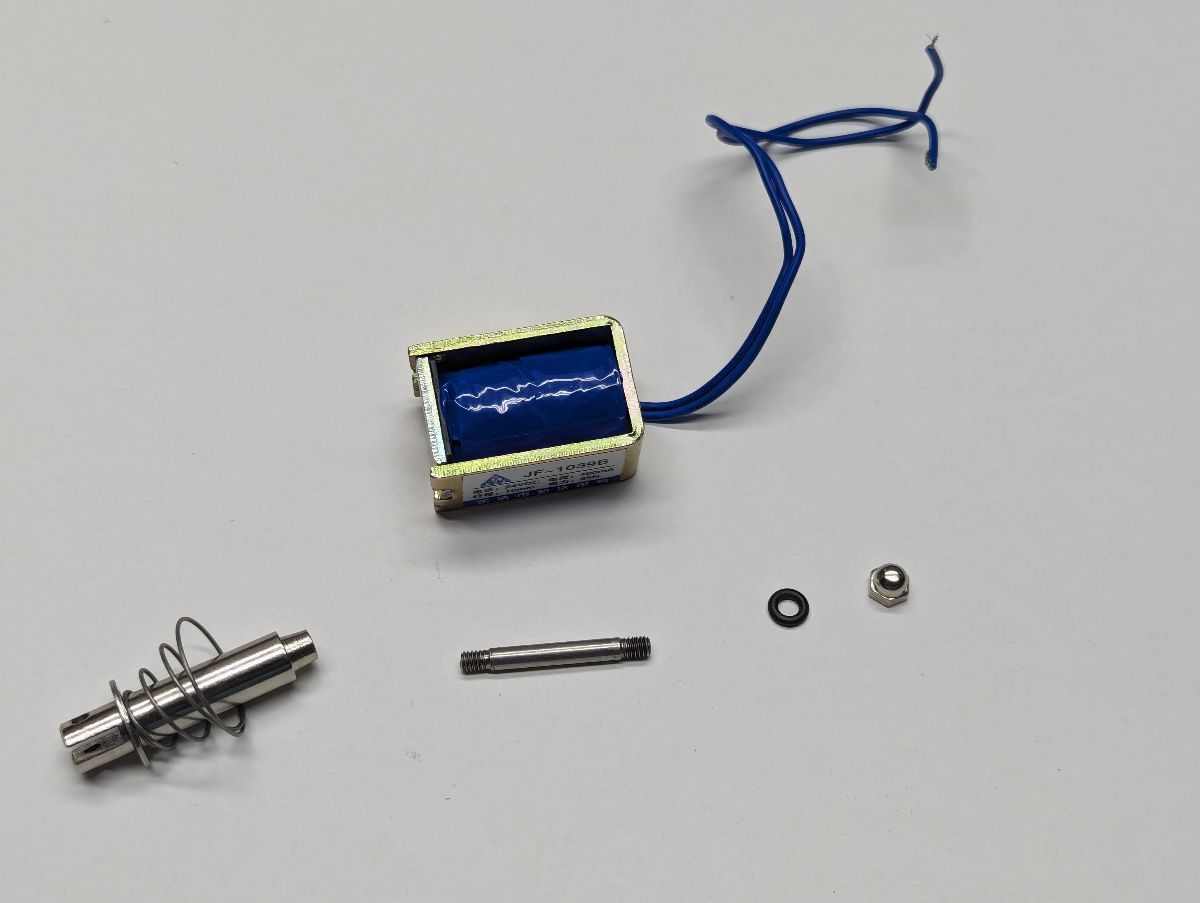
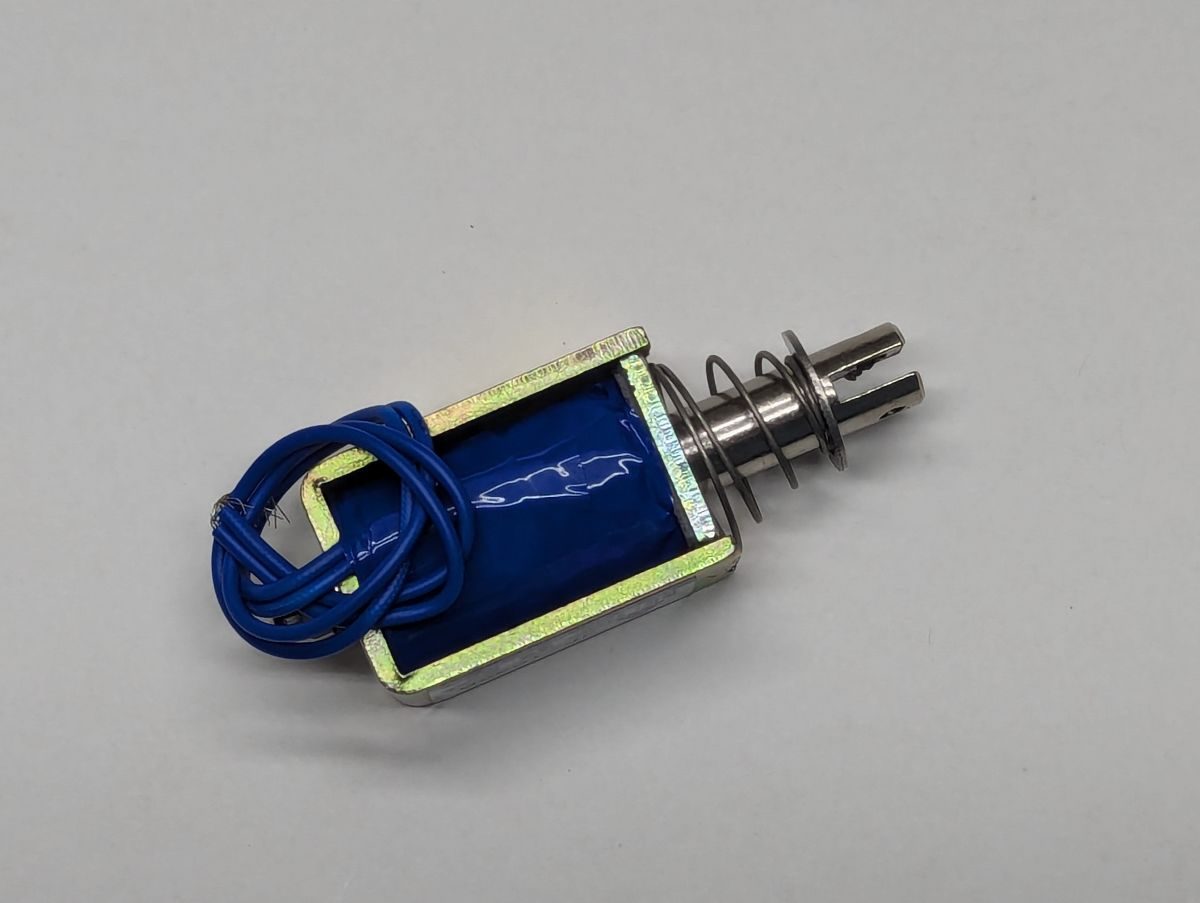
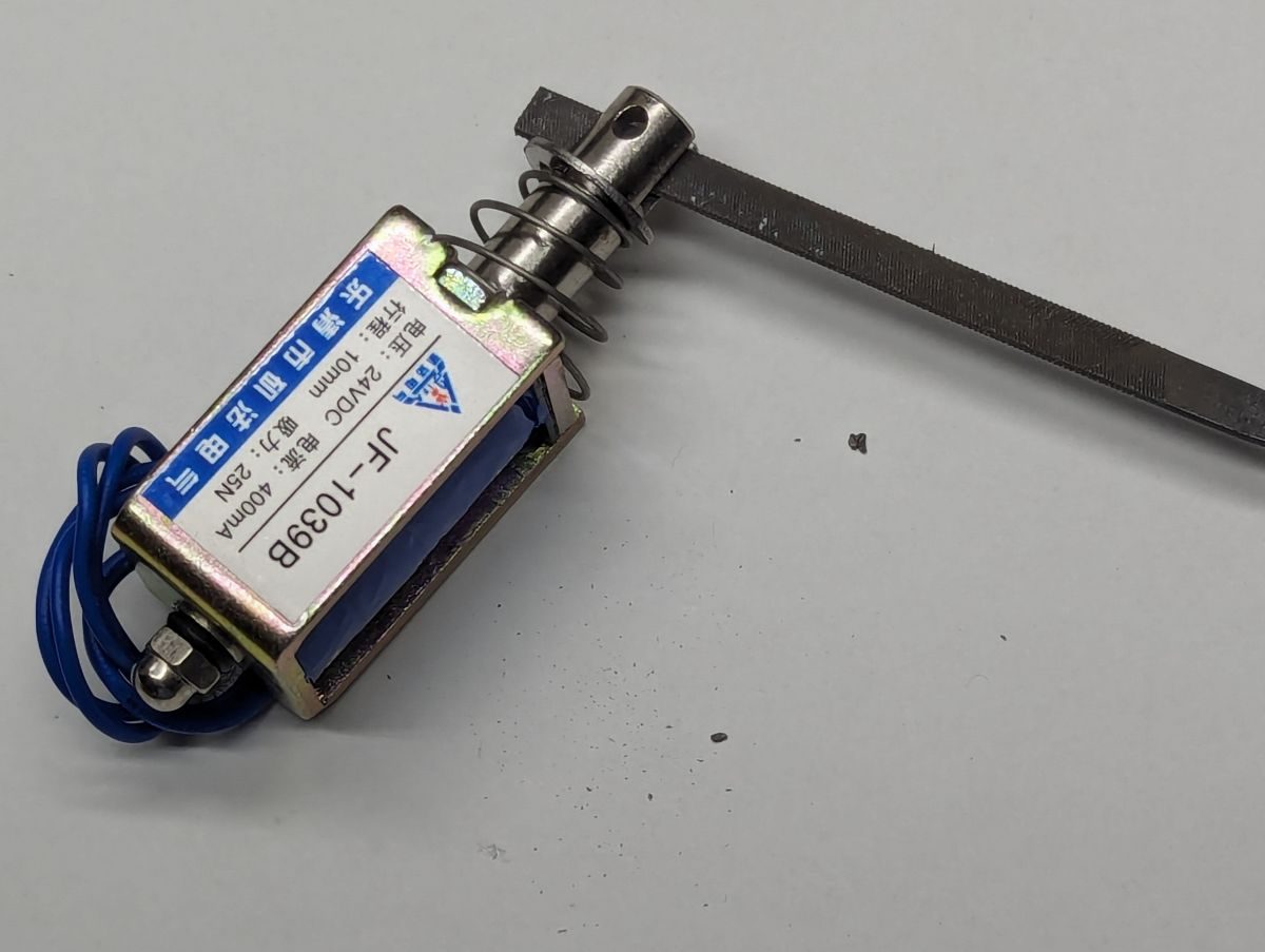
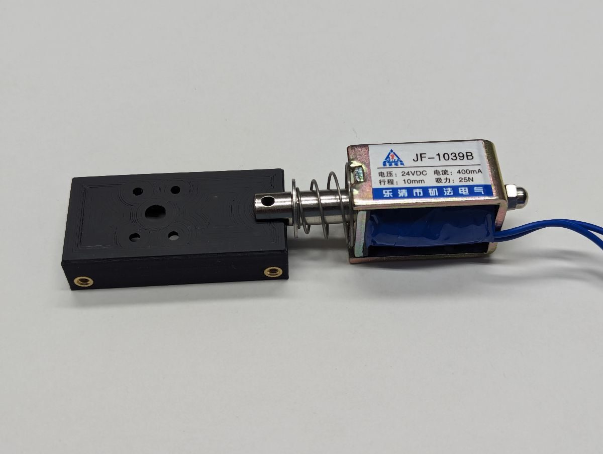
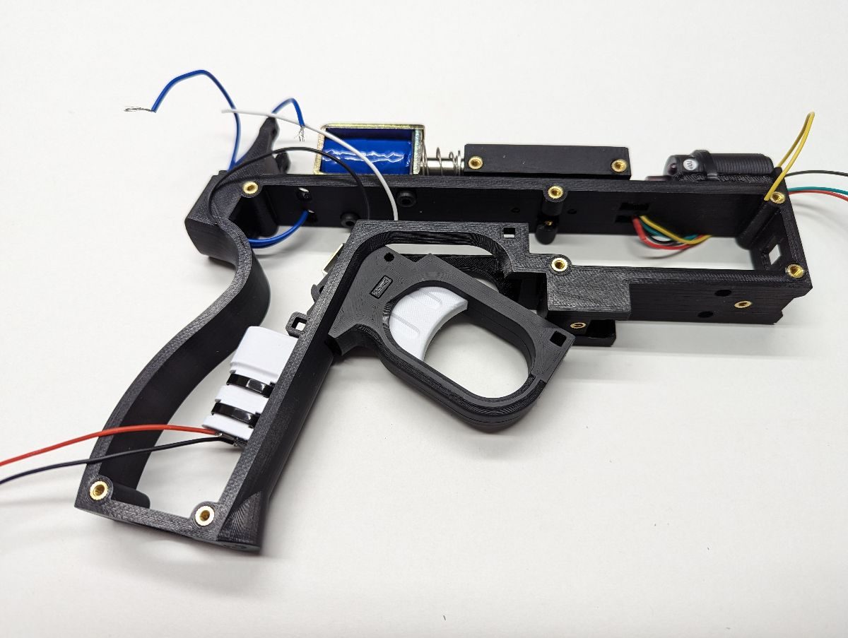
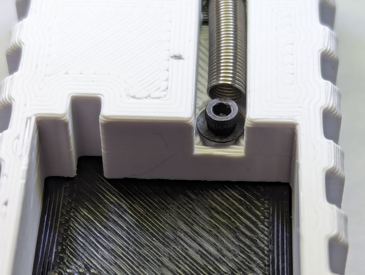
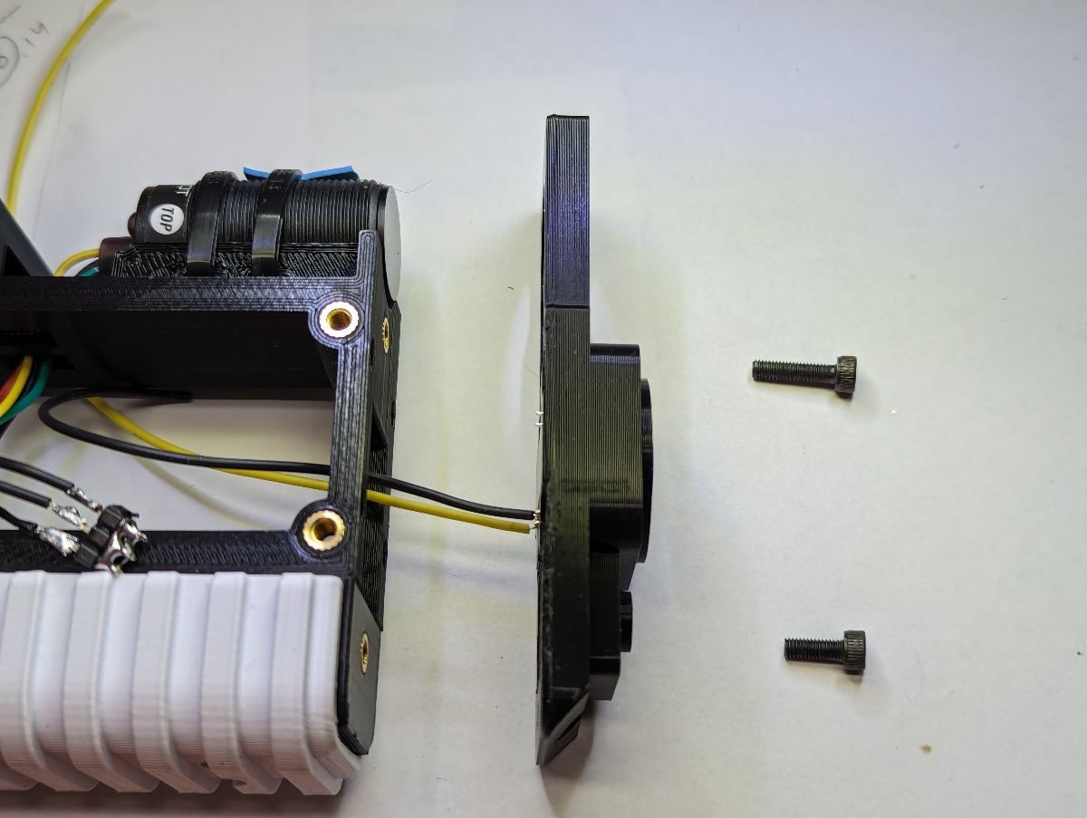
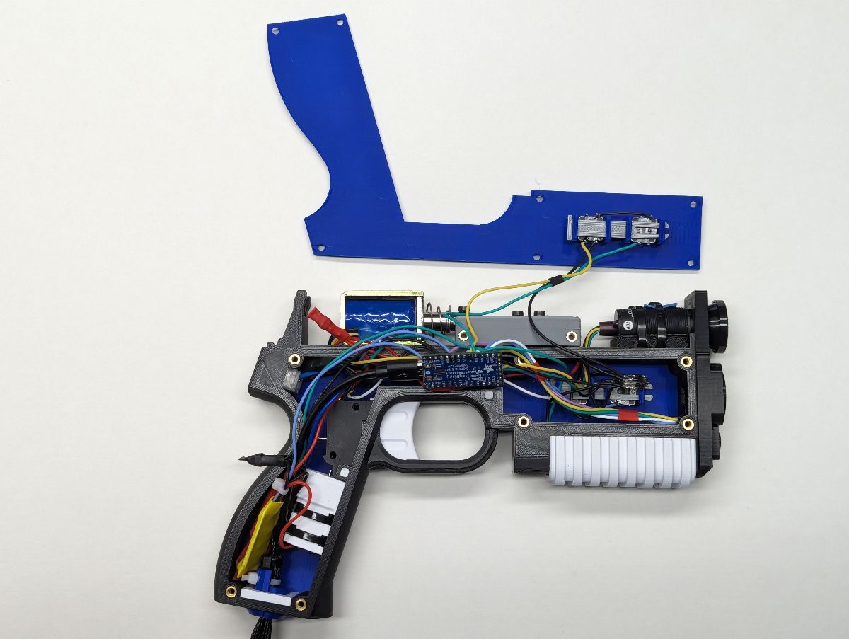
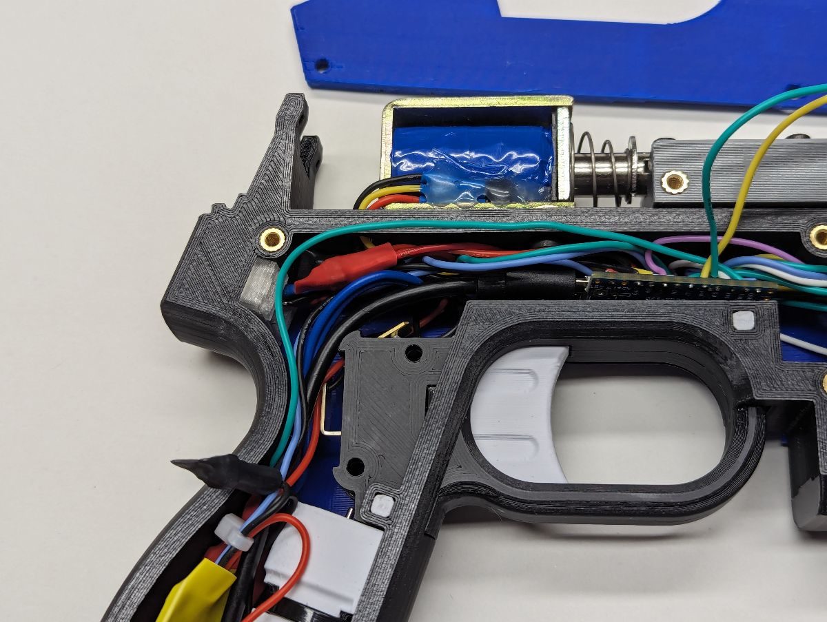
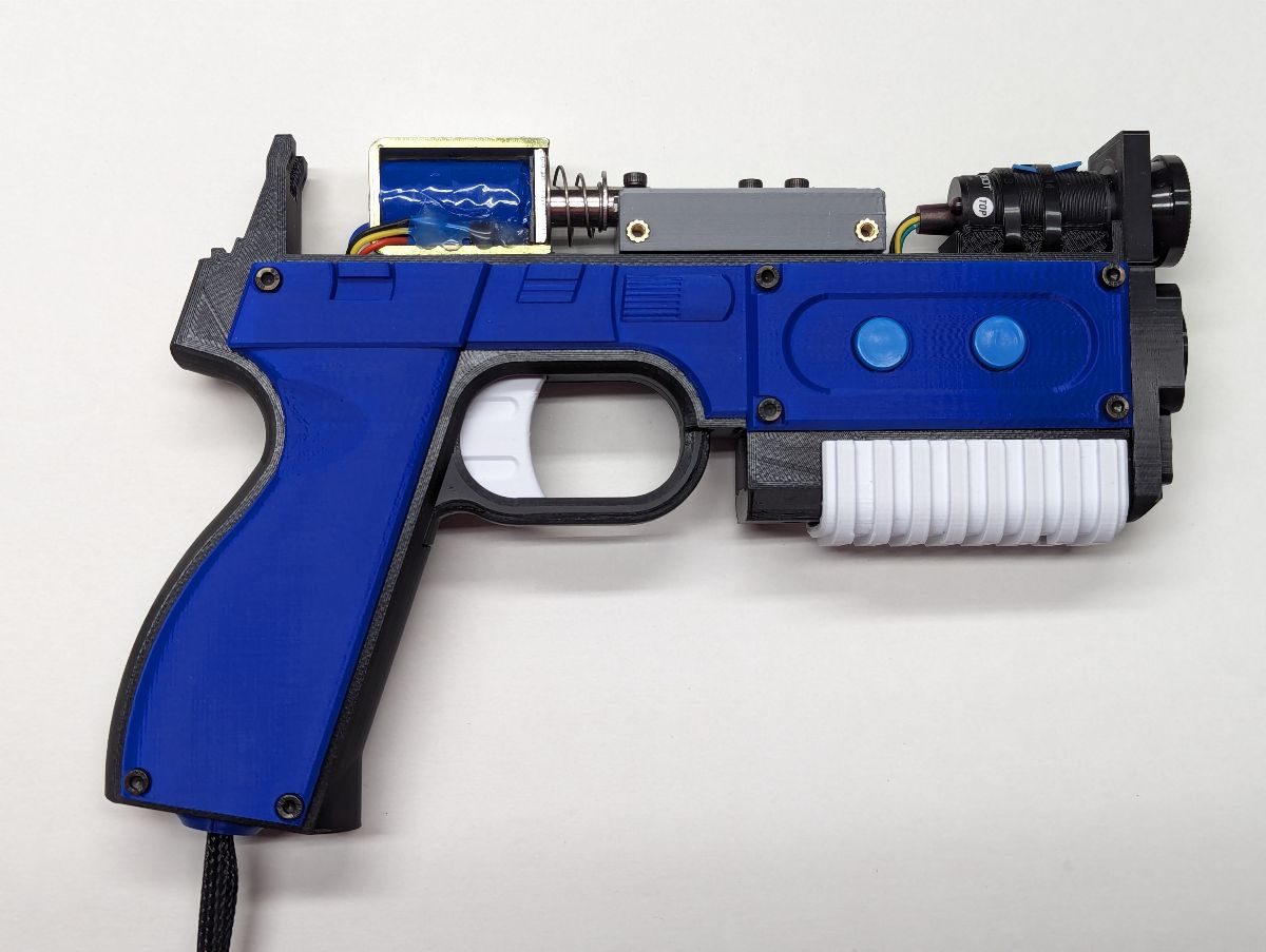
Place the solenoid on the top of the Frame and carefully slide it forward so the solenoid shaft slides into the Bearing-Solenoid Mount. Use (1) M3x12 screw to attach the solenoid shaft to the Bearing-Solenoid Mount. If you have Loctite thread locking compound, put a drop on the end of this screw before fastening it.
Do not over tighten this screw! Doing so may cause the solenoid shaft to bind.
Use (2) M4x6 screws to attach the solenoid to the Frame. Pass the solenoid wires through one of the holes in the back of the Frame.
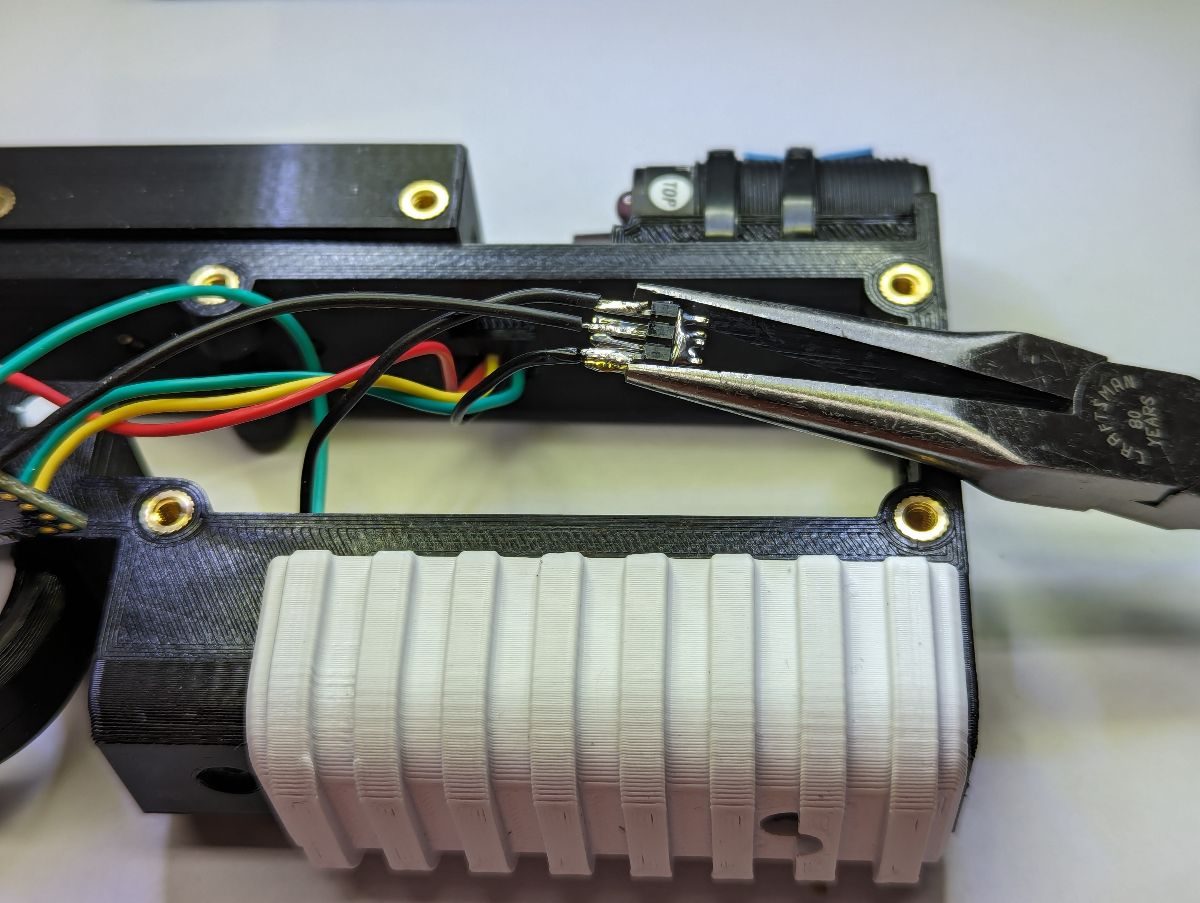
Cut two wires (28AWG or larger suggested) long enough to reach to where your solenoid driver will be. Strip and tin the ends of the wires and use needle nose pliers to bend the wire in a “J” hook. Insert the hook in the motor terminal. Squeeze the hook onto the motor terminal and solder it in place.
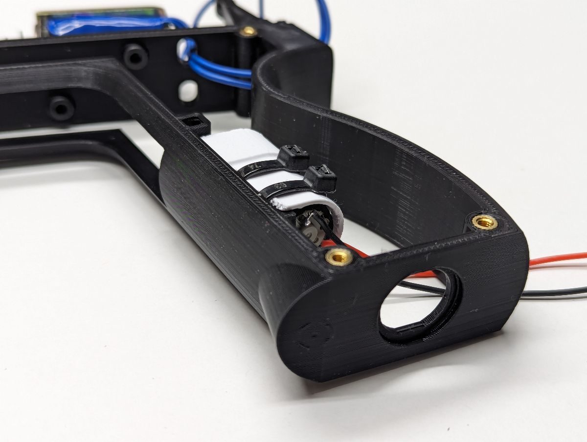
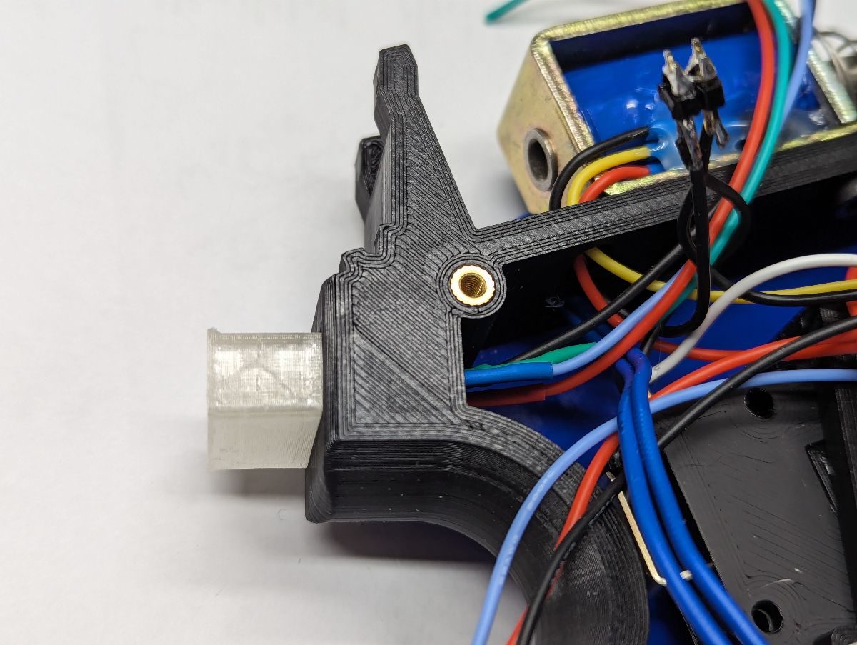
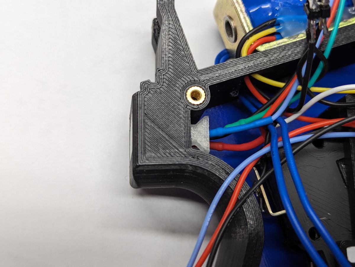
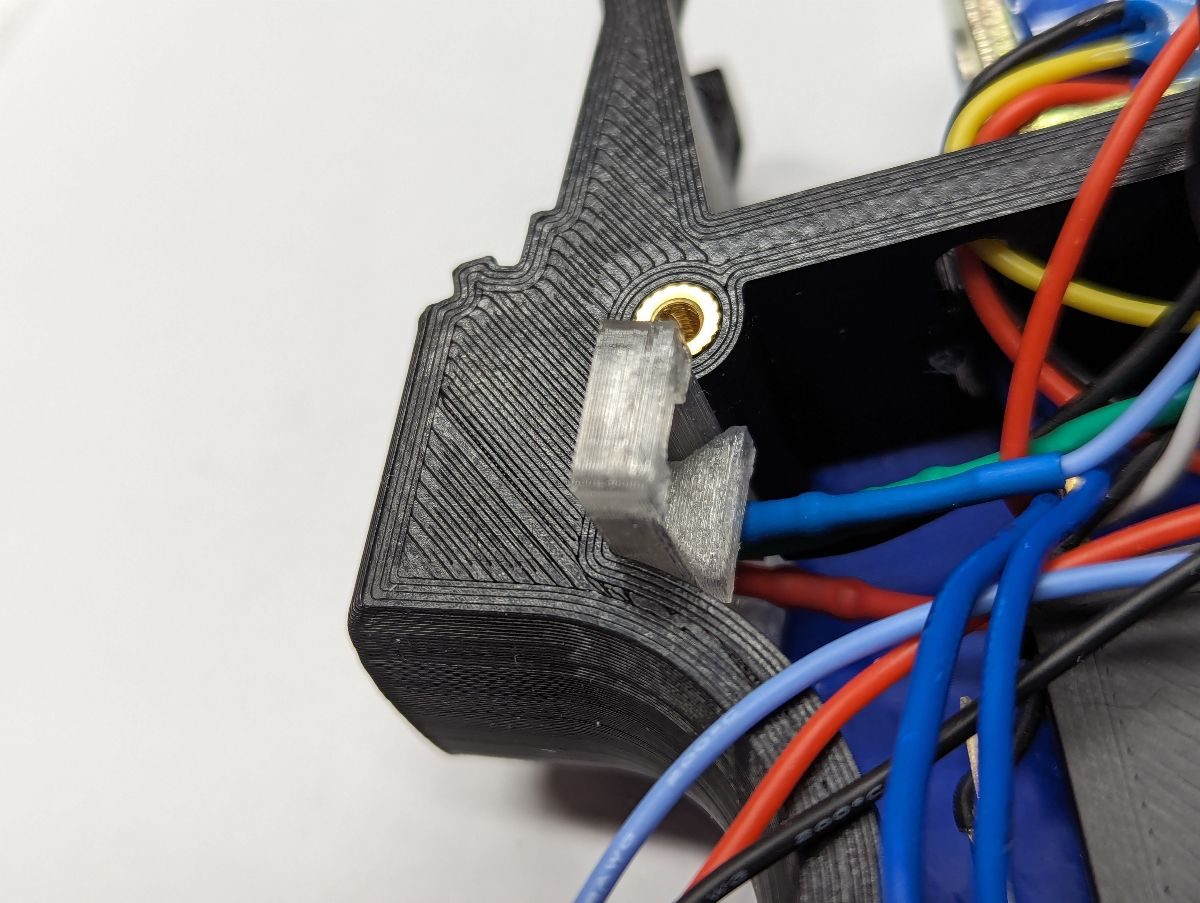
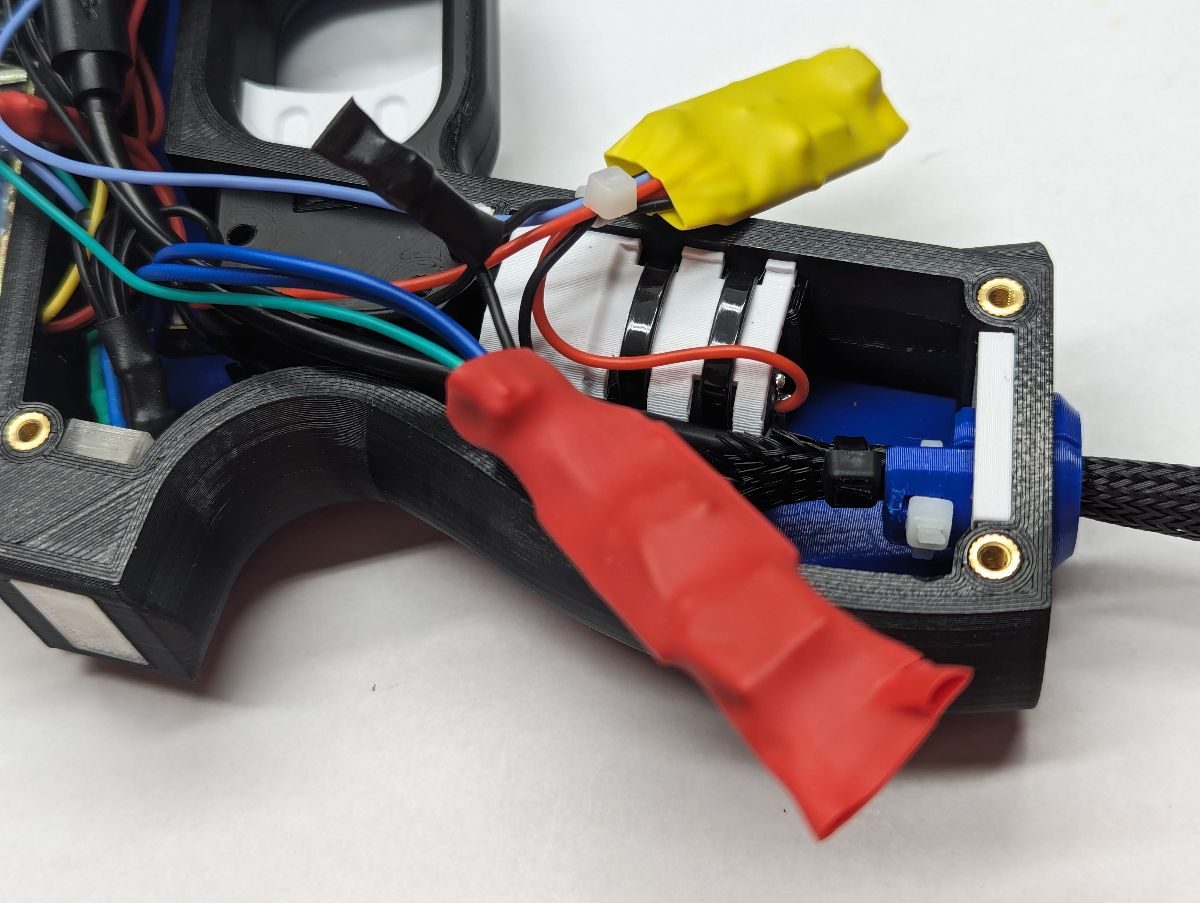
Do not remove the foam surrounding the rumble motor, this layer of foam increases the amount of vibration. Place the Rumble Guard over the rumble motor with the wide end over the motor weight. Place the rumble motor and Rumble Guard in the grip of the Frame so that the motor terminals are towards the butt of the gun and the motor weight is towards to the trigger. Use (2) zip ties to secure the rumble motor and Rumble Guard to the Frame making sure that the zip tie clasp is positioned so that it won’t interfere when the Side panel is installed.
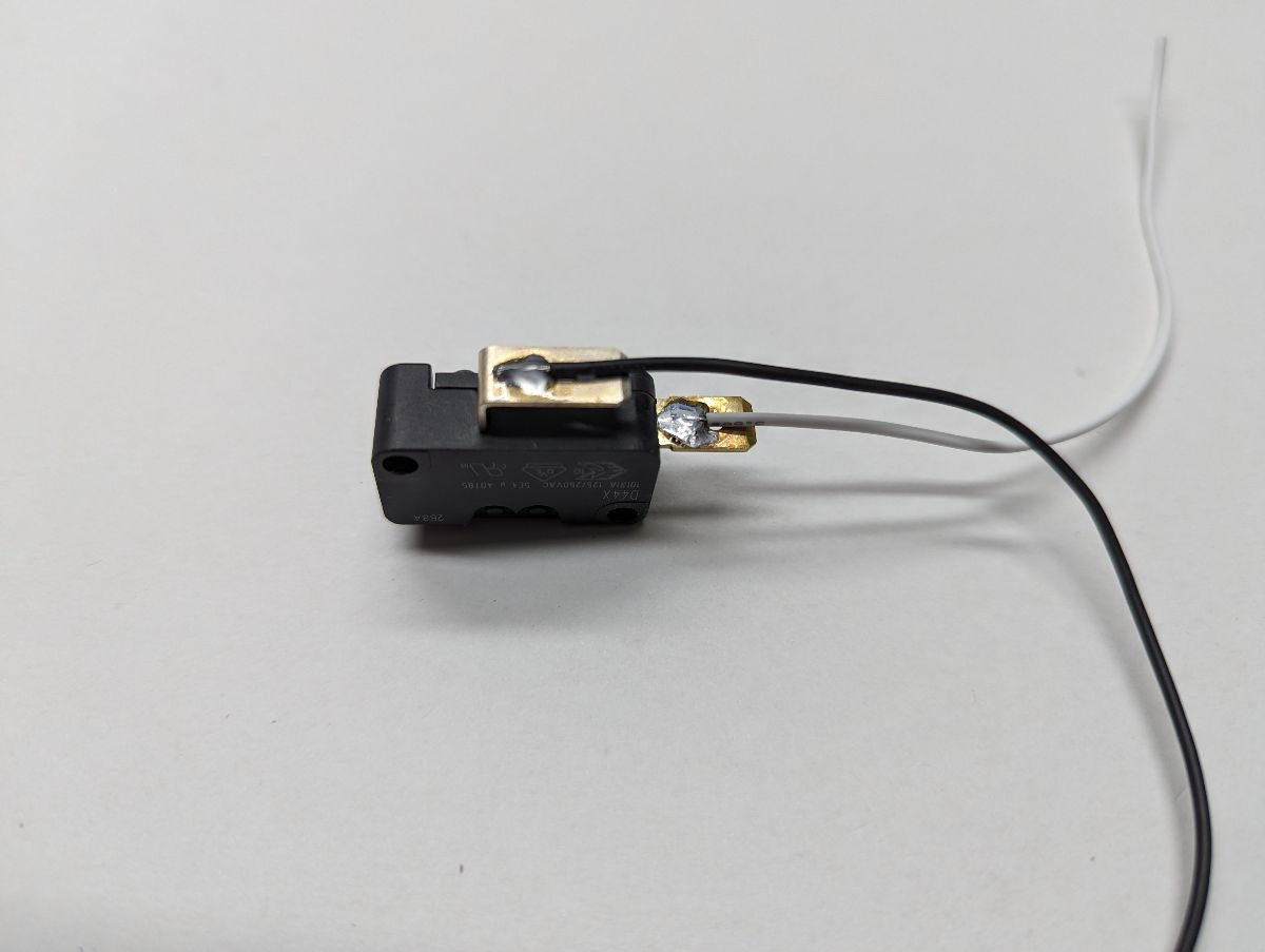
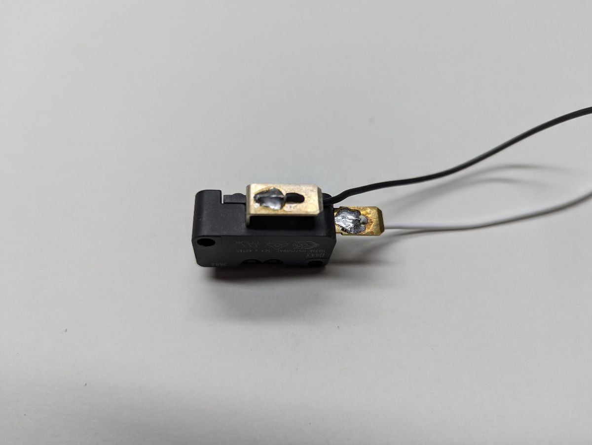
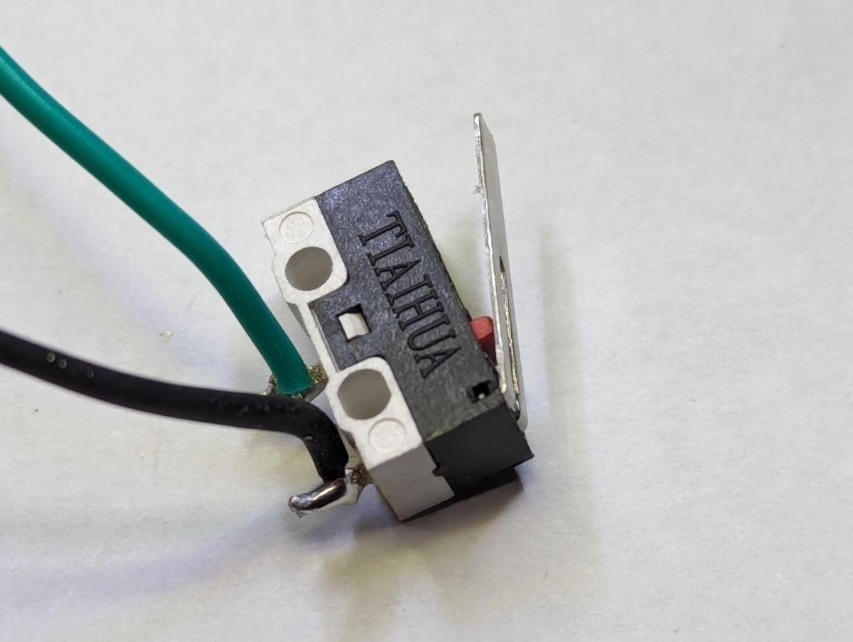
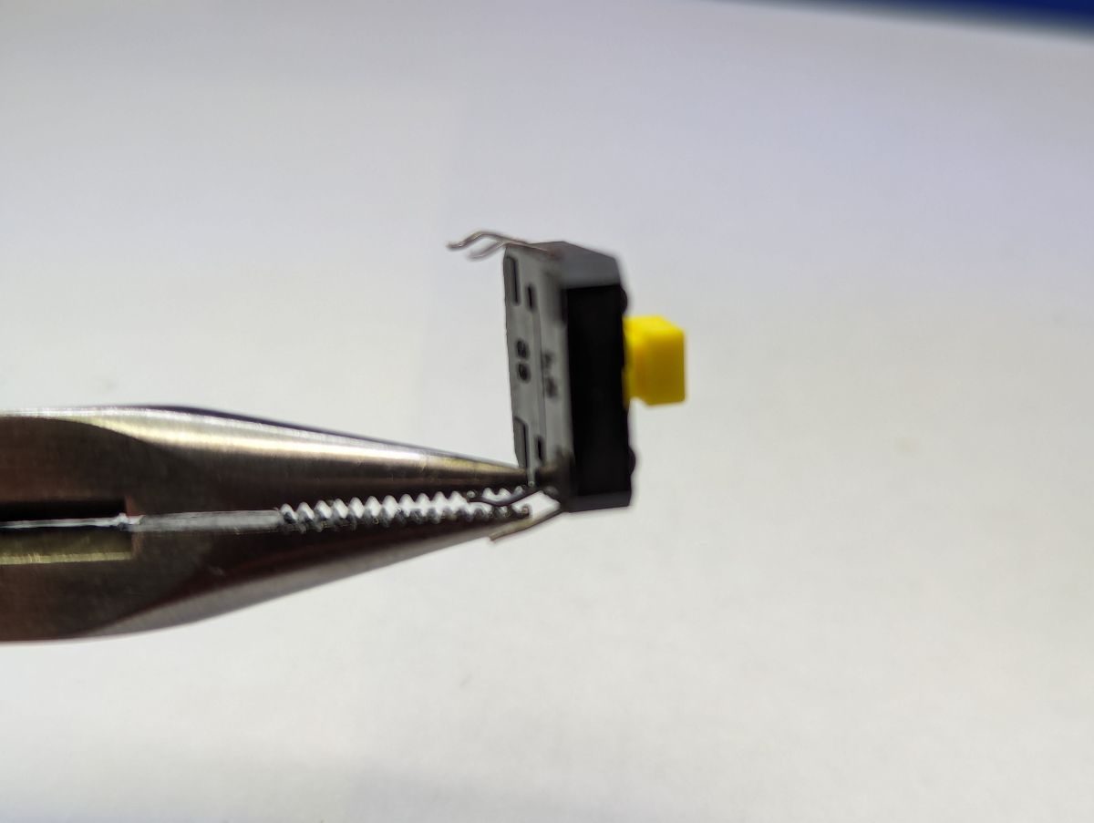
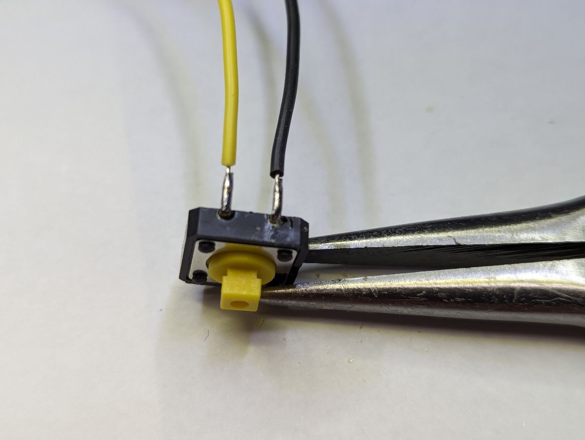
If your trigger switch has a normally closed terminal (typically labeled “NC”), use a needle nose pliers to bend the terminal back and forth repeatedly until breaks off as close to the switch body as possible. Cut two wires long enough to reach the microcontroller, strip and tin the end of each wire. Create a solder pool on the normally open and common terminals (typically labeled “NO” and “C”). Lay the tinned end of each wire in the solder pool and solder the wire in place. To avoid cold solder joints, hold the wire stead until the solder pool cools. Tuck the wires through the hole in the terminal for strain relief or use hot glue to secure the wires to the switch terminals.
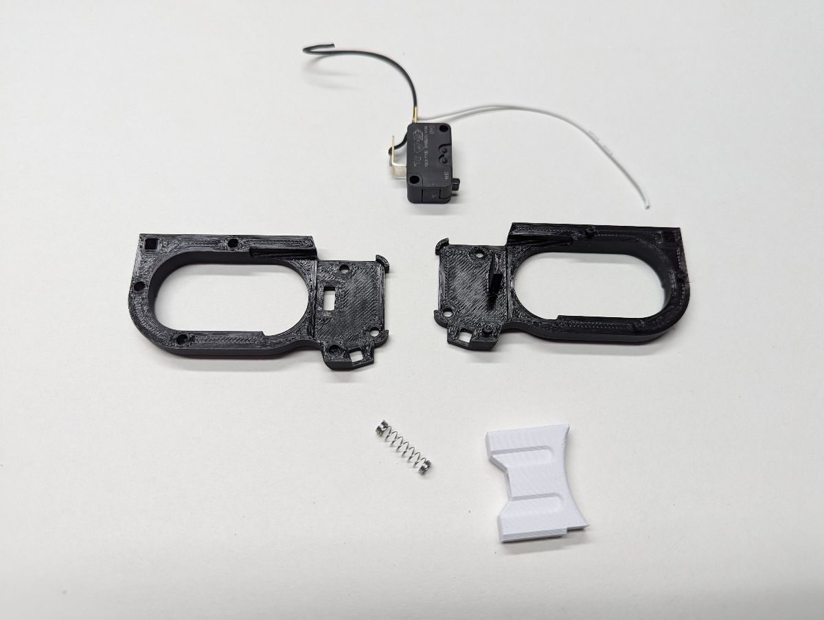
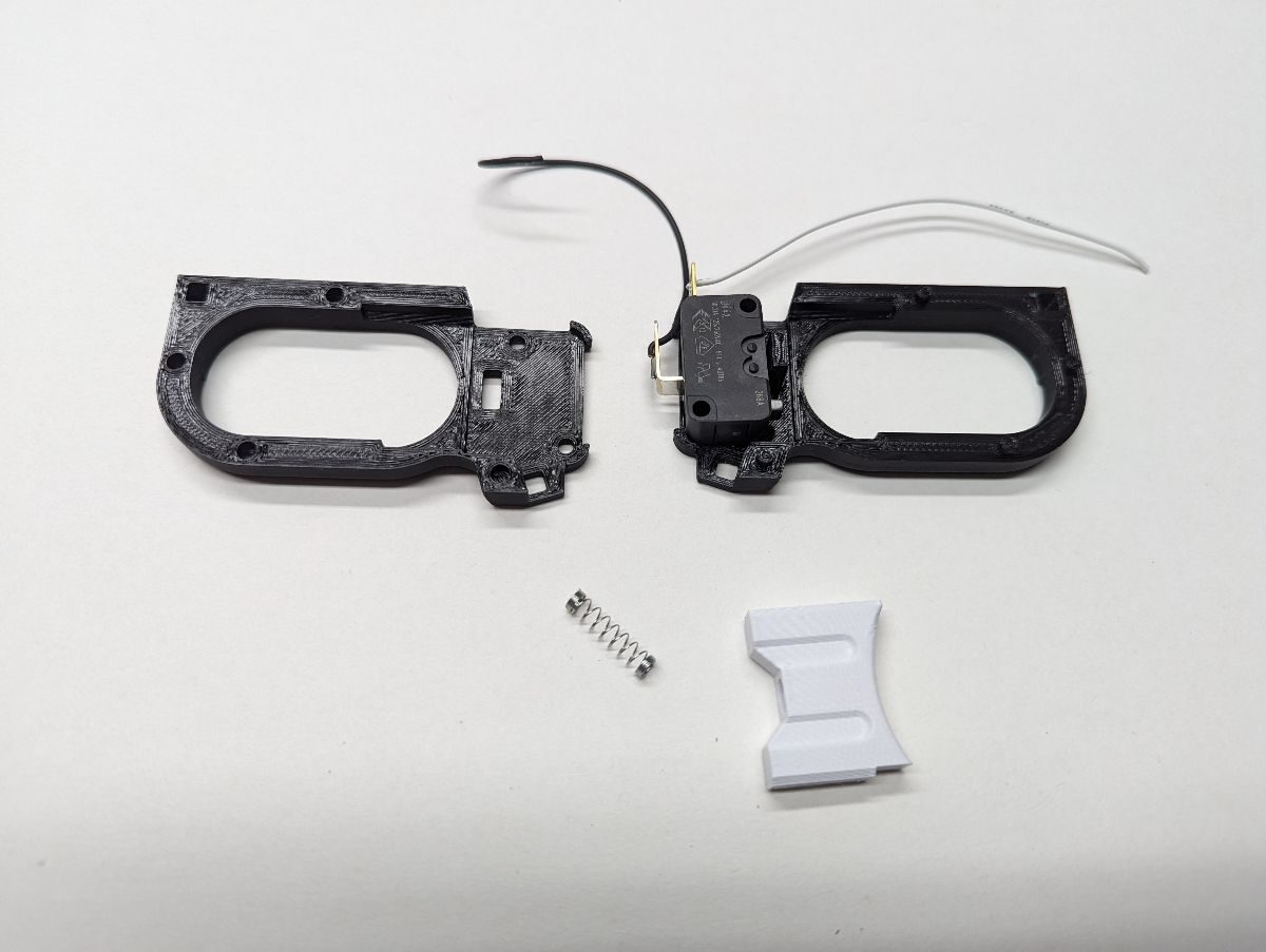
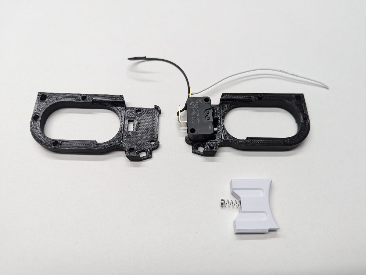
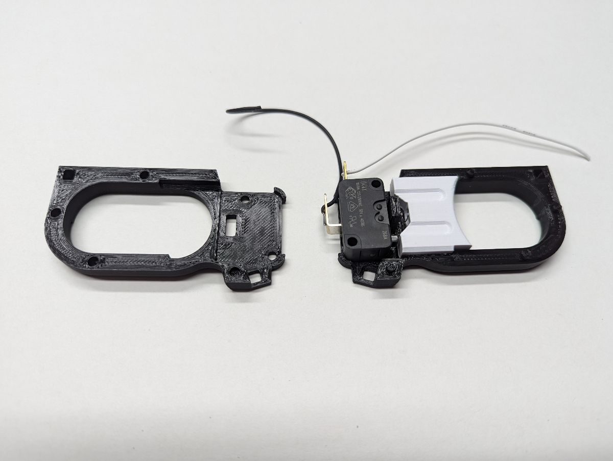
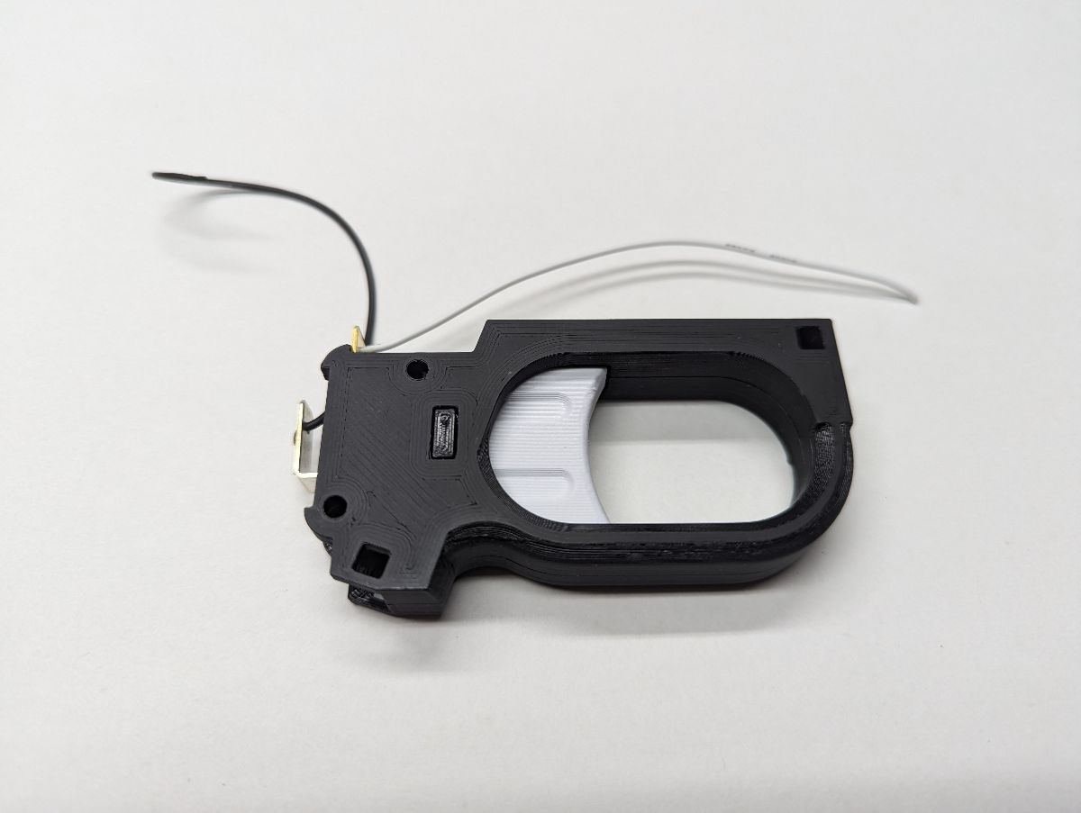
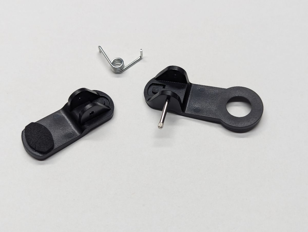
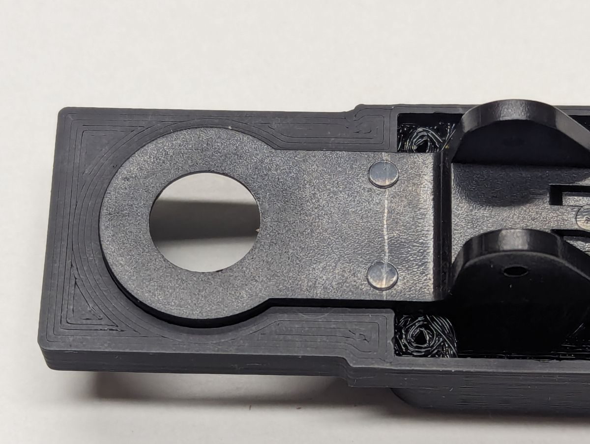
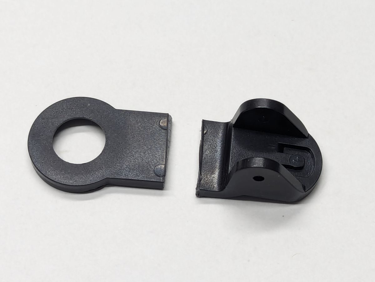
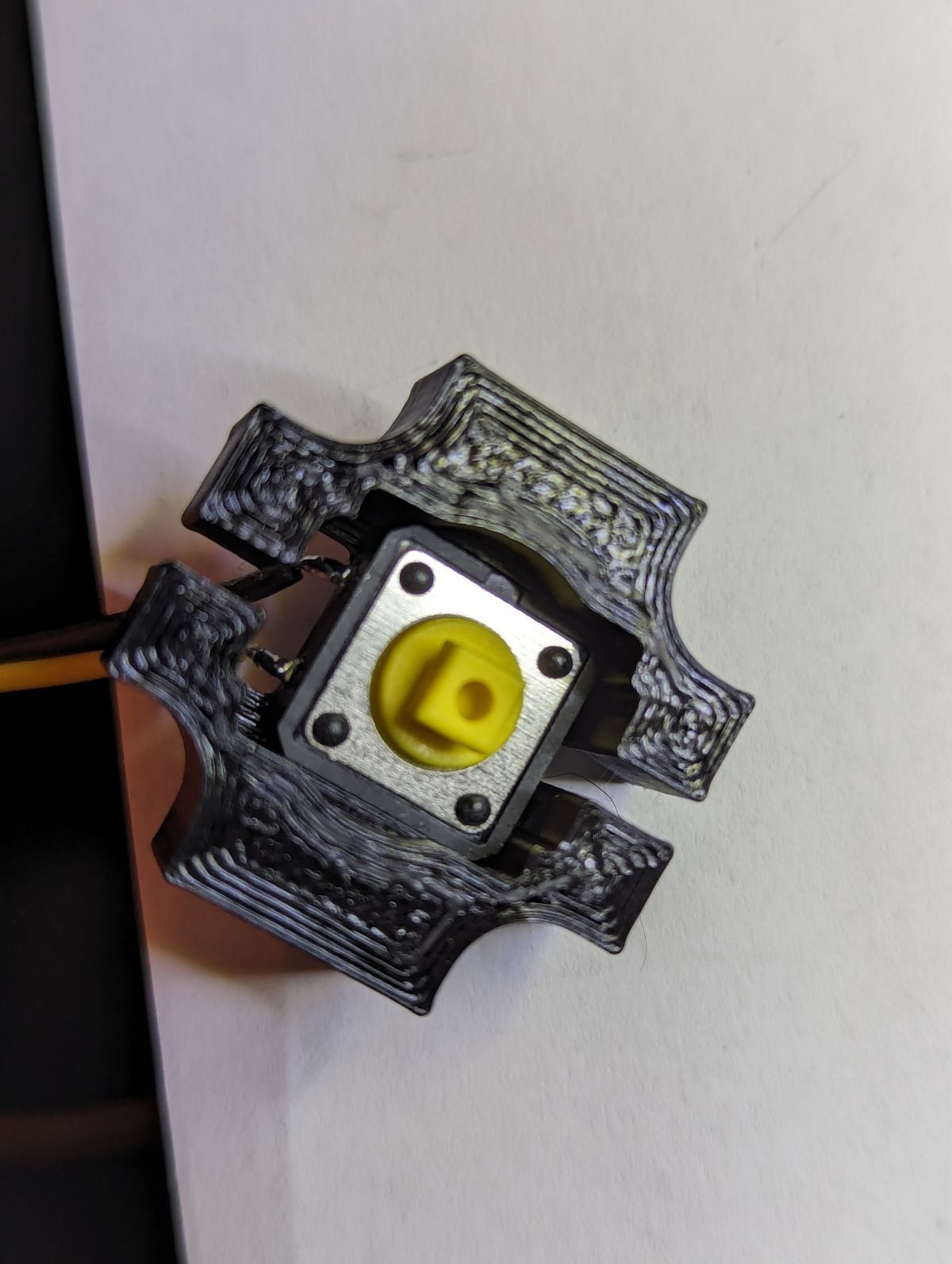
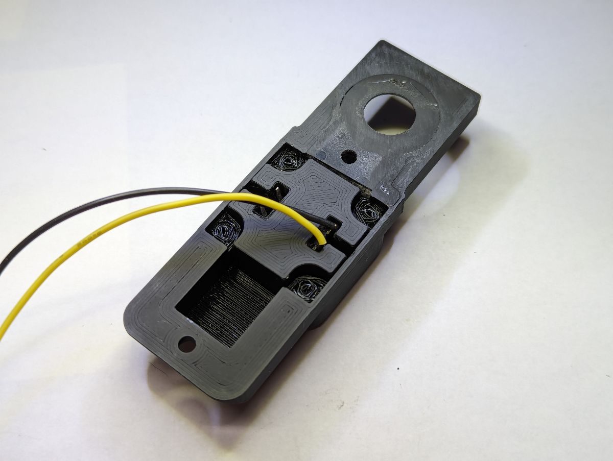
Place the trigger switch in the Left Trigger Guard. Insert a pen spring in the back of the Trigger and align the other end of the spring with the tab sticking up from the left Trigger Guard. Lay the Trigger in the left Trigger Guard with the notch towards the bottom. Place the Right Trigger Guard onto the Left Trigger Guard. Verify the trigger operates smoothly, if it does not sand or file any z-seams on the Trigger that may be interfering. Insert the trigger assembly into the opening in the Frame switch first. Rotate the trigger assembly into position in the Frame so the square holes align. Insert the Trigger Guard Pins into the square holes to secure the trigger assembly in place.
Place the trigger switch in the Left Trigger Guard. Insert a pen spring in the back of the Trigger and align the other end of the spring with the tab sticking up from the left Trigger Guard. Lay the Trigger in the left Trigger Guard with the notch towards the bottom. Place the Right Trigger Guard onto the Left Trigger Guard. Verify the trigger operates smoothly, if it does not sand or file any z-seams on the Trigger that may be interfering. Insert the trigger assembly into the opening in the Frame switch first. Rotate the trigger assembly into position in the Frame so the square holes align. Insert the Trigger Guard Pins into the square holes to secure the trigger assembly in place.
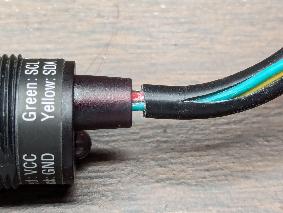
To allow the IR camera wires to make the tight turns that will be required, it is necessary to remove the outer insulation. A 3d printable tool is available to make removing the outer insulation easier. Using the tool, slit the entire length of the outer insulation. Locate the slit on at the end of the cable and spread it apart slightly. Grab all 4 wires and pull them through the slit. Use caution when you get close to the camera body to prevent ripping the camera apart. The front of the DF Robot camera has a protective film. To remove this film, place a piece of tape over the front of the camera and rub the tape on the film for good adhesion. Pull the tape off and the film should stick to the tape.
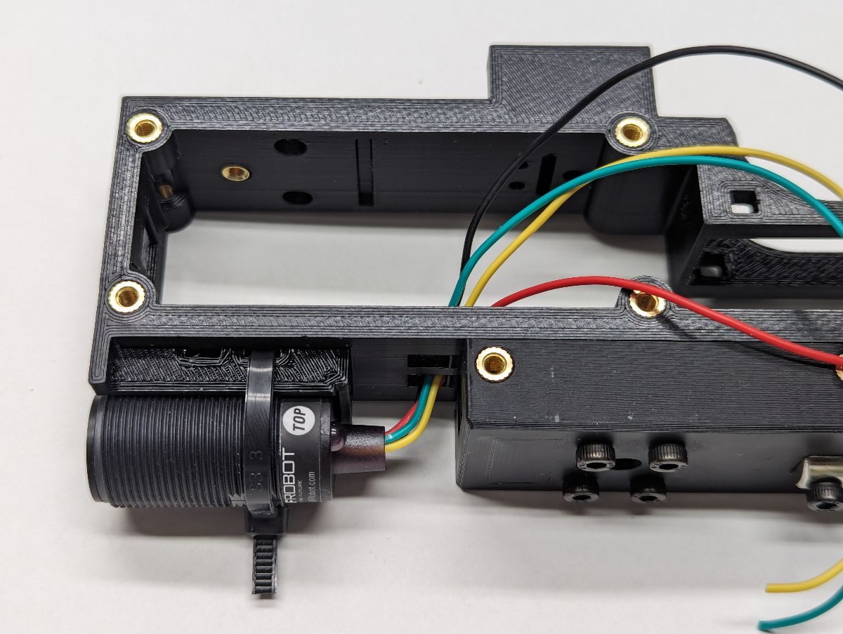
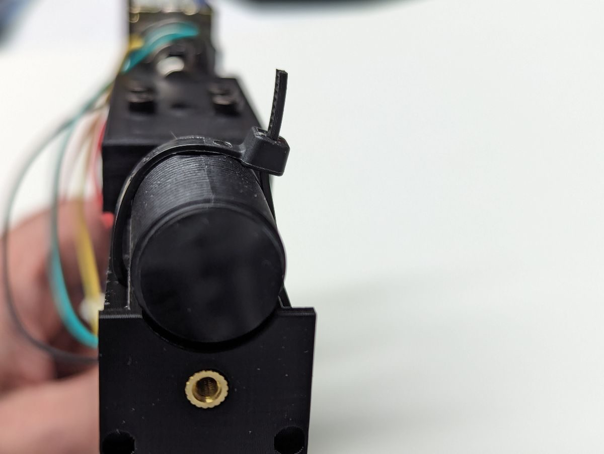
Place the IR camera in the top front of the Frame. Ignore the “TOP” indicator on the camera, it is most likely wrong. For Gun4IR builds, install the camera so the camera wires are on the left and the camera LED indicator is on the right (when looking from the back of the lightgun). For Samco/Prow/Gun4All builds, the wires will be on the right and the LED indicator on the left. Pass a zip tie through the rear zip tie hole in the Frame below the camera and secure the camera to the Frame making sure that the zip tie clasp is positioned so that it won’t interfere when the Slide is installed. Do not cut the excess zip tie yet. Do not install the second zip tie yet, this will be done after the camera alignment is verified. Pass the camera wires through the hole in the Frame one at a time.
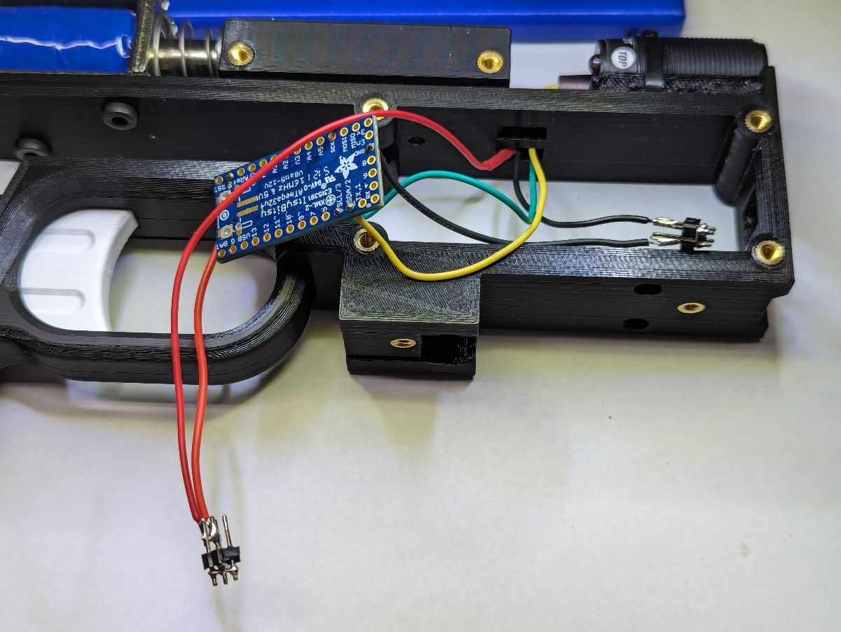
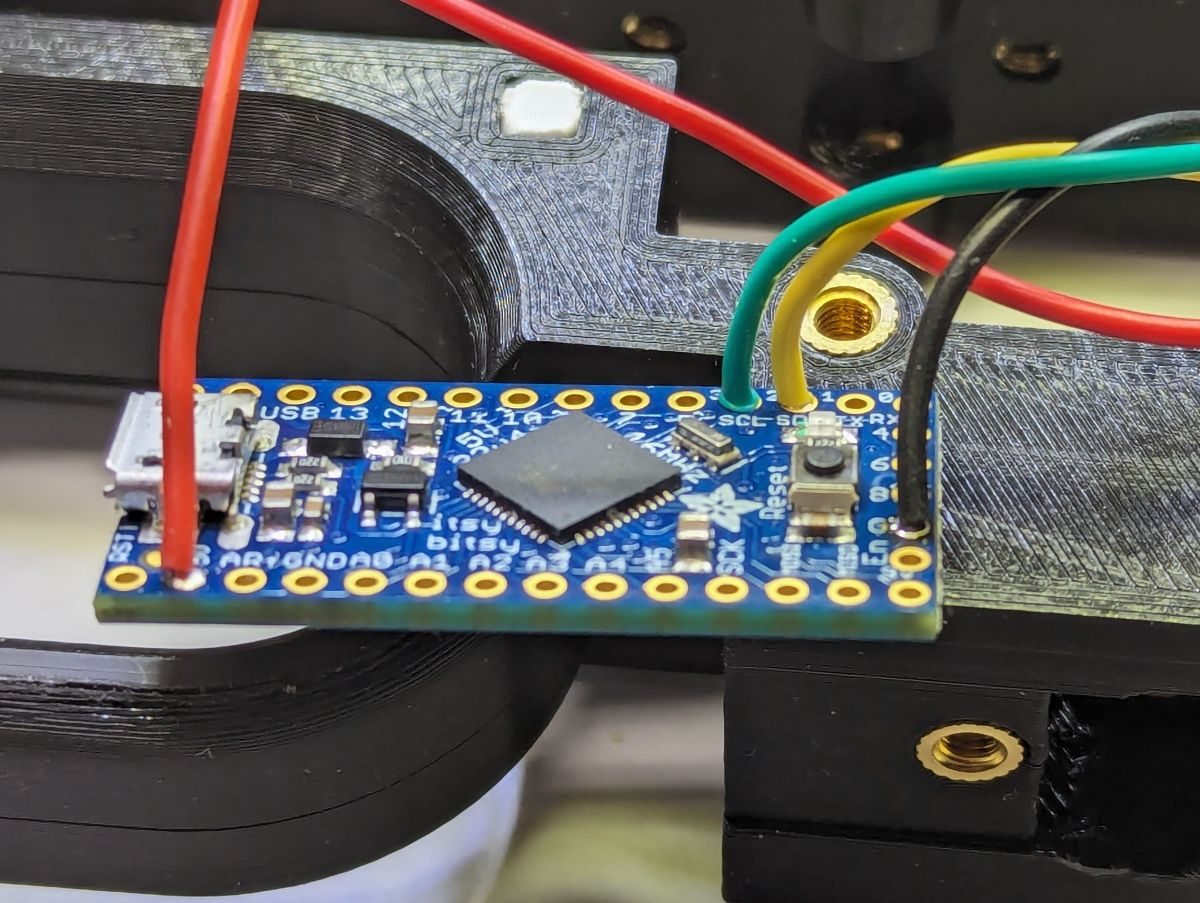
Determine where your microcontroller will be located in the lightgun. Typically, this will be directly above the trigger assembly. I recommend inserting the wires into the top of the microcontroller so that the wires will prevent the microcontroller from making contact with the solenoid screws located above. One wire at a time, cut your camera wire at the appropriate length and solder it to the microcontroller. Remember that the ground and 5v wires will likely need to be soldered to a distribution block rather than directly to the microcontroller. The sticker on the camera shell shows the color of the wires for each signal.
Determine where your microcontroller will be located in the lightgun. Typically, this will be directly above the trigger assembly. I recommend inserting the wires into the top of the microcontroller so that the wires will prevent the microcontroller from making contact with the solenoid screws located above. One wire at a time, cut your camera wire at the appropriate length and solder it to the microcontroller. Remember that the ground and 5v wires will likely need to be soldered to a distribution block rather than directly to the microcontroller. The sticker on the camera shell shows the color of the wires for each signal.
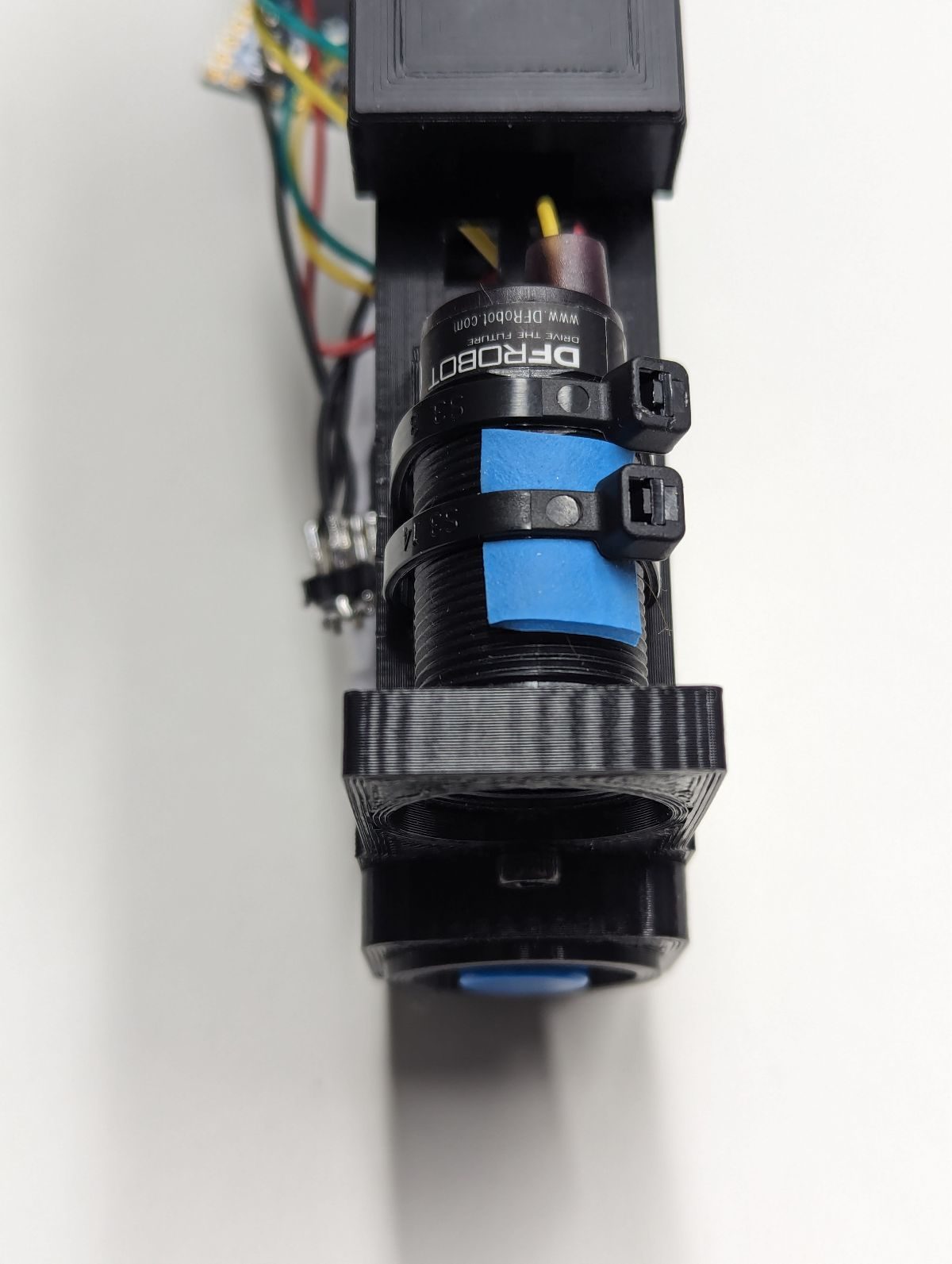
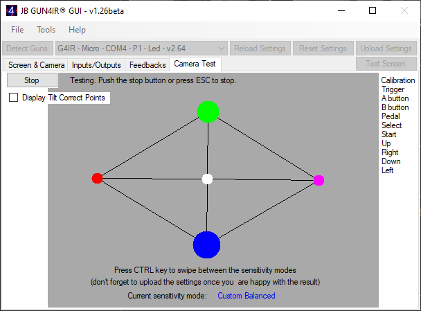
Plug in the USB cable to the microcontroller and plug the other end into your PC. Start the Gun4IR GUI Windows application and open the Camera Test screen. Turn on your IR LEDs (sensors, emitters, whatever you want to call them) and verify that 4 IR spots are detected by the camera (since there is no lens on the camera yet, you may need to back up far enough). While holding the lightgun perfectly vertical, rotate the camera in the front of the lightgun until the cross formed by the 4 spots on the GUI are horizontal and vertical. Insert a zip tie in the frame hole below the center of the camera and a piece of rubber band between the zip tie and the top of the camera shell. Tighten the zip tie to lock the camera in place. Double check the horizontal and vertical alignment and use a pair of needle nose pliers to firmly grasp the tail of the zip tie and rotate the pliers to tighten the zip ties one last notch. Disconnect the USB cable from the microcontroller. The horizontal and vertical alignment need to be close but do not need to be perfect since the firmware will dynamically adjust to small deviations in tilt.
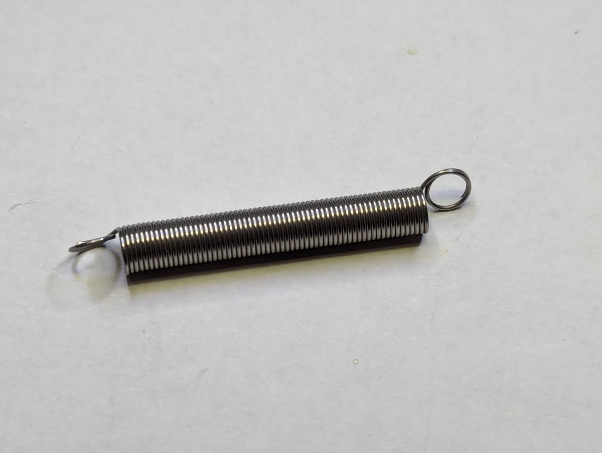
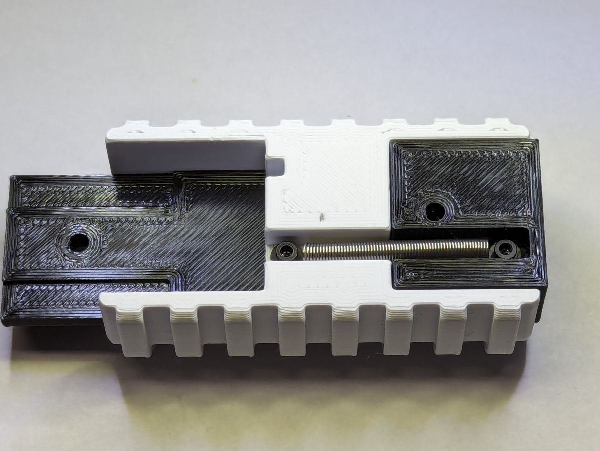
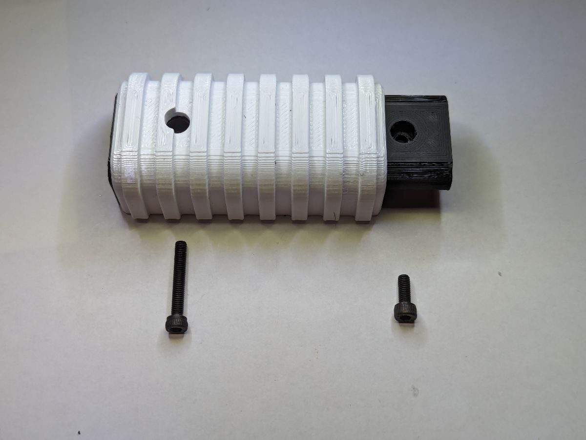
Cut the pump spring to a length of 27mm (1-1/8”). Bend the last one or two loops of the pump spring at a 90-degree angle. Create another loop at the other end of the spring such that both loops are facing close to the same direction. Install an M2 washer on a M2x6 screw. Insert the screw and washer through the loop that was formed at the end of the pump spring and insert the screw end into the front of the Pump Mount. Tighten the screw until it just touches the spring loop. Do not over tighten this screw to prevent stripping the threads formed in the plastic. Slide the Pump onto the Pump Mount so the spring channel aligns with the channel in the Pump Mount. Install another M2 washer on a M2x6 screw. Insert the screw and washer through the loop at the other end of the pump spring and insert the screw end into the Pump. The spring should be in slight tension, if not shorten your spring. Tighten the screw until it just touches the spring loop. Do not over tighten.
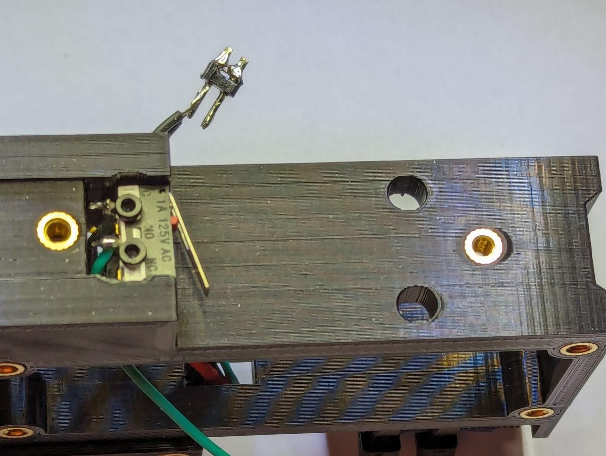
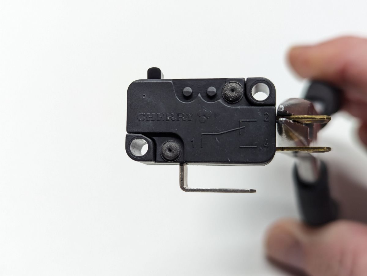
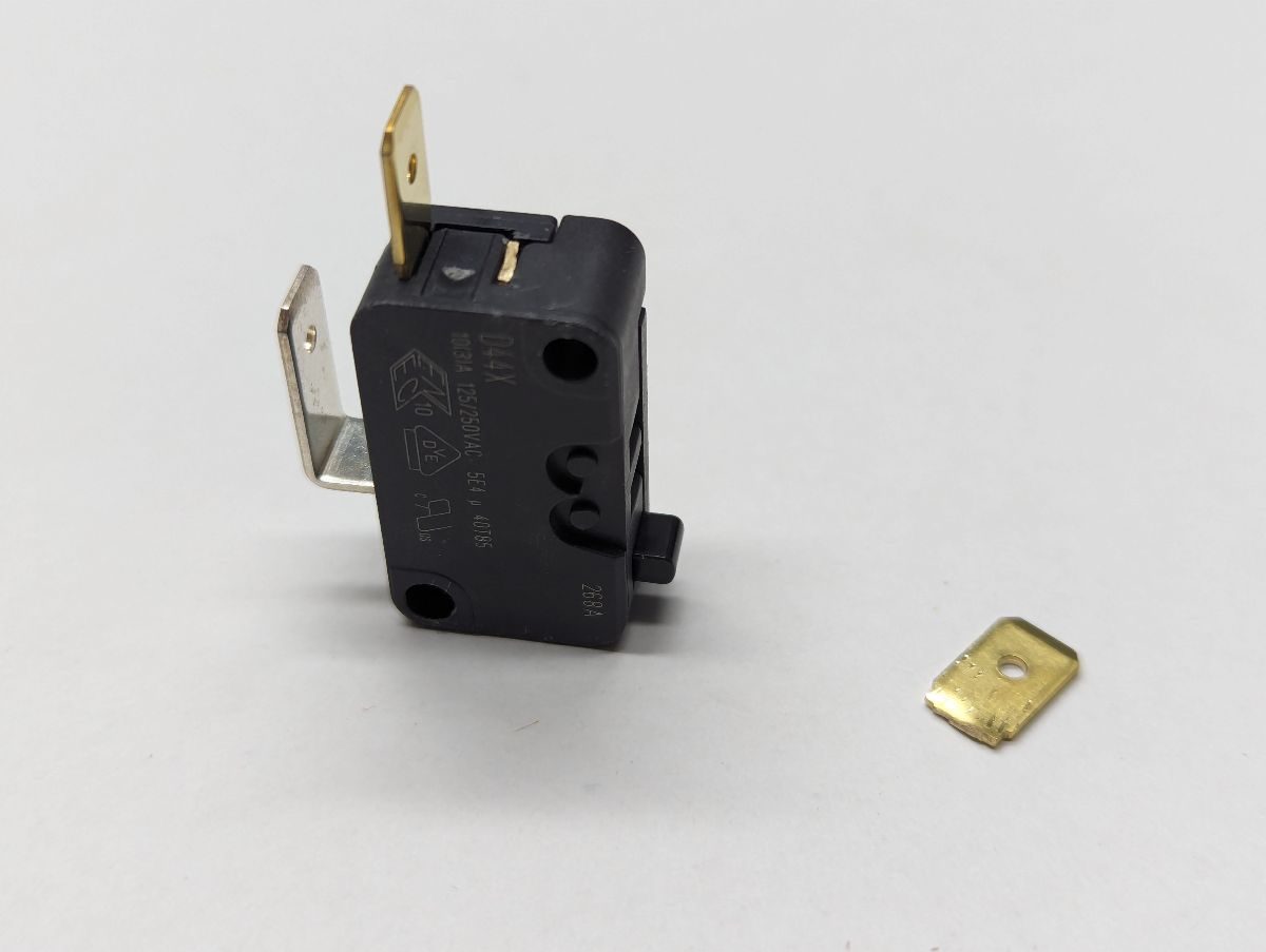
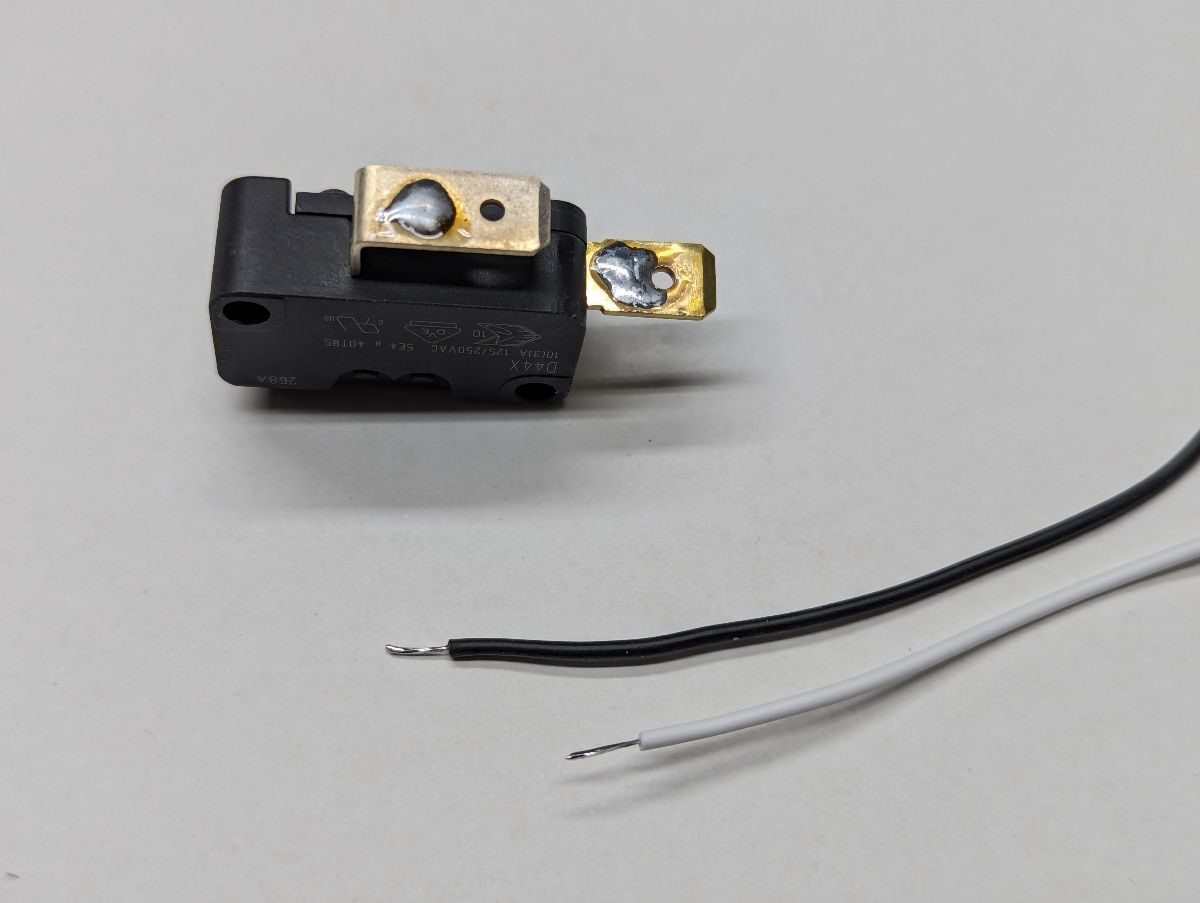
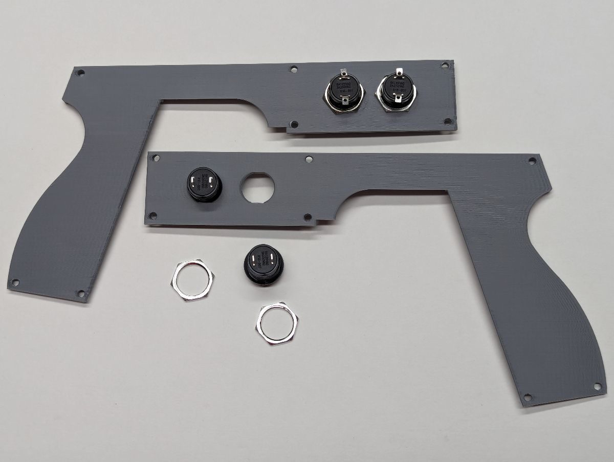
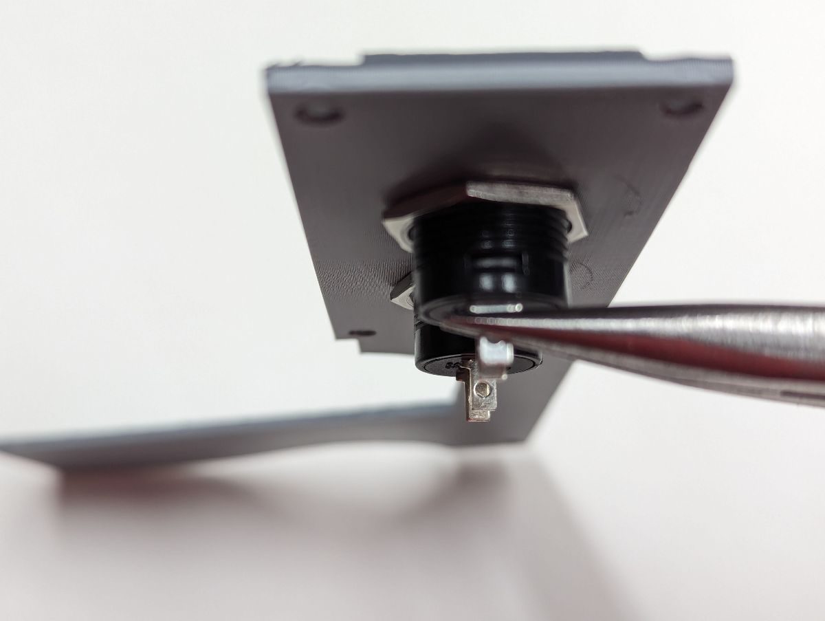
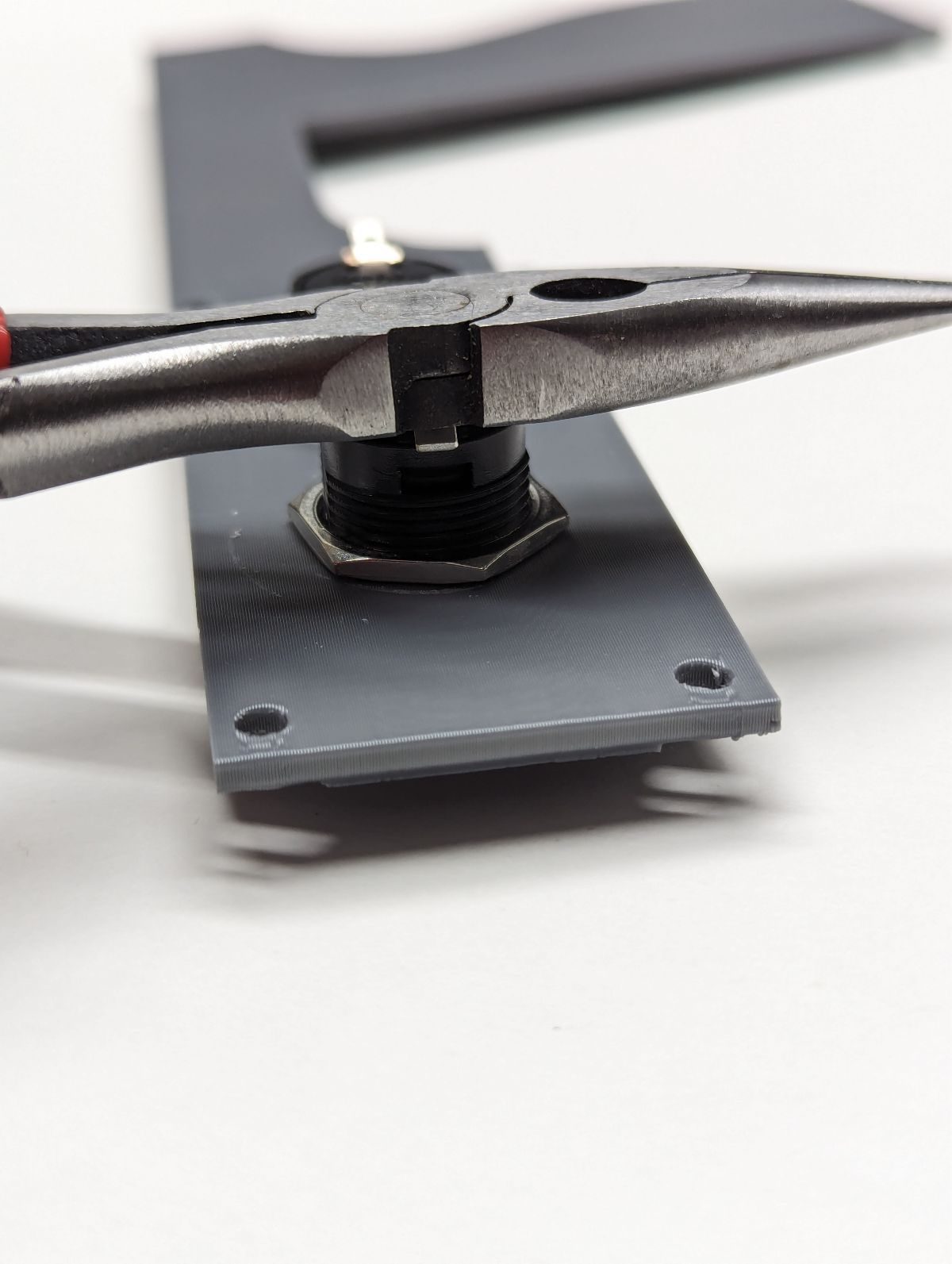
Cut the normally closed terminal (typically labeled “NC”) from the pump switch. Cut two wires that will be used to connect the pump switch to the microcontroller. Strip and tin the end of each wire. Use needle nose pliers to bend the tinned wires 180 degrees to form a hook. Place the hooked wire over the common switch pin and squeeze the hook to the pin. Solder the wire. Repeat this process to connect a wire to the normally open terminal (typically labeled “NO”). Push the wires through the slot in the Frame behind the switch. If you installed M2 heat set inserts to mount the pump switch to the Frame, use (2) M2x12 screws to attach the switch to the Frame as shown. If you did not use M2 heat set inserts, use (2) M2x16 screws, washers and nuts to attach the switch to the Frame.
Cut the normally closed terminal (typically labeled “NC”) from the pump switch. Cut two wires that will be used to connect the pump switch to the microcontroller. Strip and tin the end of each wire. Use needle nose pliers to bend the tinned wires 180 degrees to form a hook. Place the hooked wire over the common switch pin and squeeze the hook to the pin. Solder the wire. Repeat this process to connect a wire to the normally open terminal (typically labeled “NO”). Push the wires through the slot in the Frame behind the switch. If you installed M2 heat set inserts to mount the pump switch to the Frame, use (2) M2x12 screws to attach the switch to the Frame as shown. If you did not use M2 heat set inserts, use (2) M2x16 screws, washers and nuts to attach the switch to the Frame.
Secure the pump assembly to the frame using (1) M3x20 screw in the hole of the Pump and (1) M3x12 screw in the hole of the Pump Mount. Solder the common terminal wire to the ground distribution block and the normally open terminal wire to the Pedal input of the microcontroller. This allows the Pump to have different capabilities than soldering it parallel to the A button.
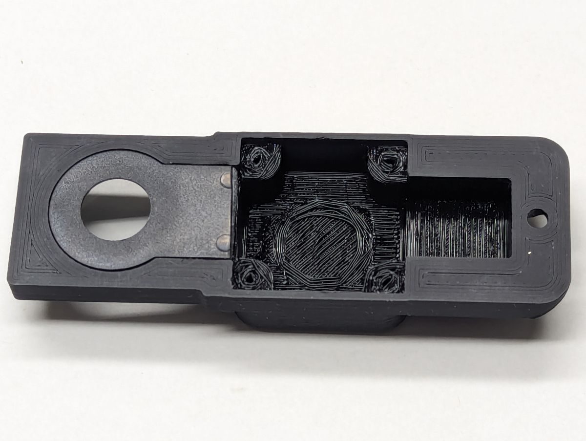
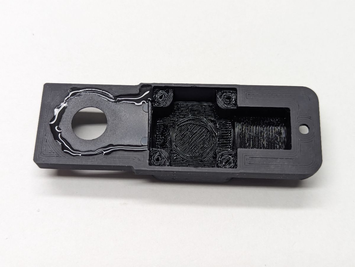
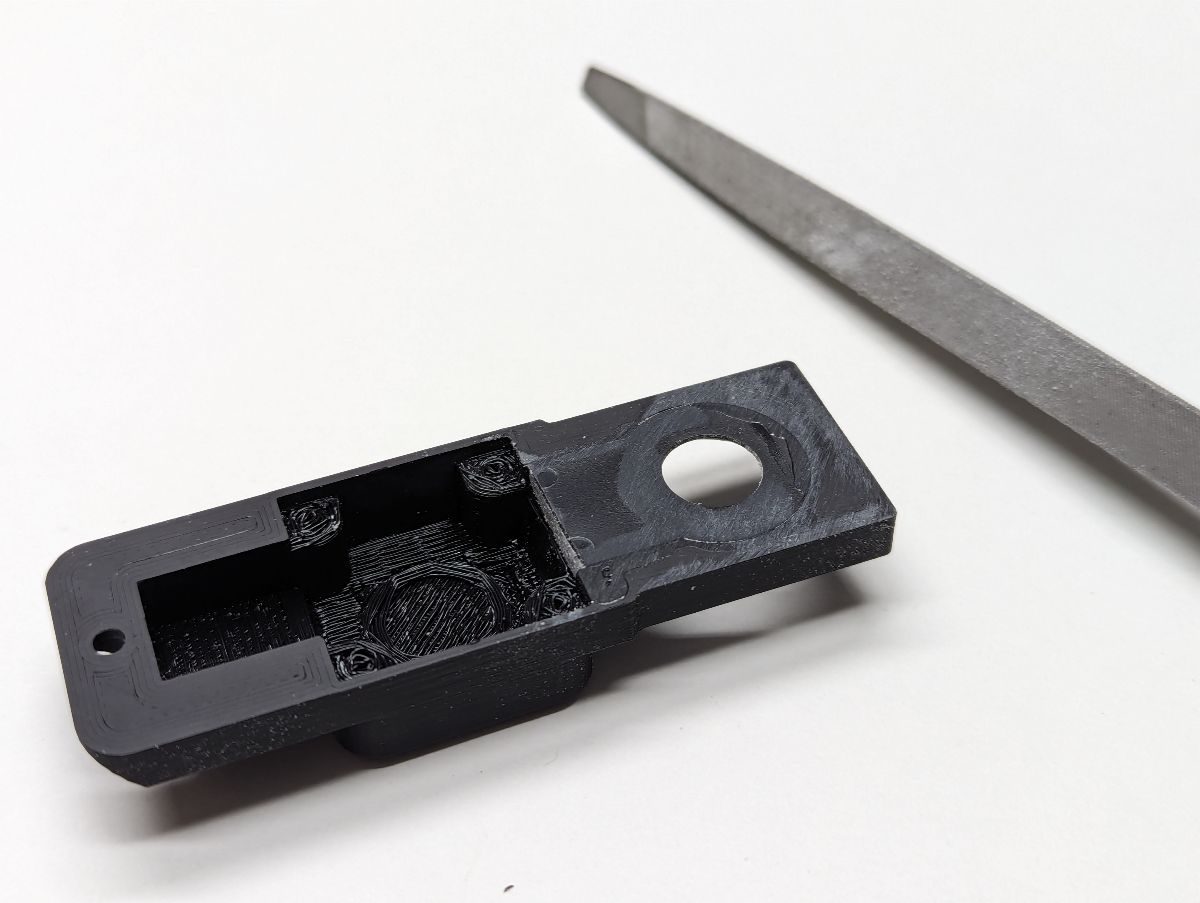
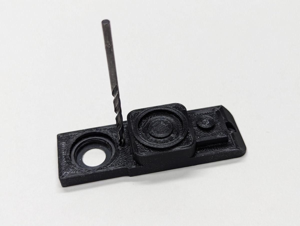
The PiCON reuses the lens holder that clips on a cell phone. Carefully push the hinge pin out of the lens holder and separate the two plastic pieces. These pieces are spring loaded so firmly hold both sides of the clip while pushing the hinge pin out. Use an Xacto or utility knife to score both sides of the threaded lens holder piece at the line shown. Score both sides several times, the deeper you score, the more accurate the cut will be. Snap the lens holder in two pieces, hopefully they break apart at the score line. Press the piece with the threads into the Front so that it lays perfectly flush. If it does not fit, file or sand the sides of lens holder if there is a bump in the injection molding. If it does not fit flat, use a flat head screwdriver to flatten any sagging overhang filament. Run a bead of superglue along the seam. After the glue is hardened, file or sand off any bumps in the glue so that it will later fit flush with the Frame. Use a 3mm (1/8”) drill bit to drill a hole through the front of the Front and through the lens holder. This hole will later be used to fasten the Front to the Frame.
If you are installing a 12x12mm pushbutton in the Front, cut, strip and tin two wires to attach to the pushbutton. User needle nose pliers to flatten the switch terminals. Solder both wires to one side of the pushbutton. Insert the pushbutton wires into Front Button Spacer, install a cap on the pushbutton and insert the pushbutton and the Front Button Spacer into the Front. Pass the two wires through the large square hole in the front of the Frame. Solder one wire to the ground distribution block and the other wire to the mode input pin of the microcontroller.
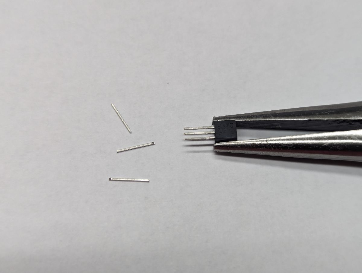
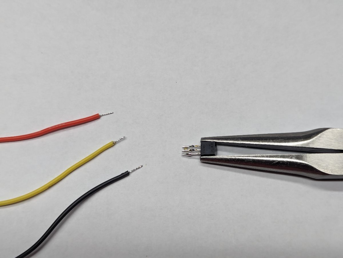
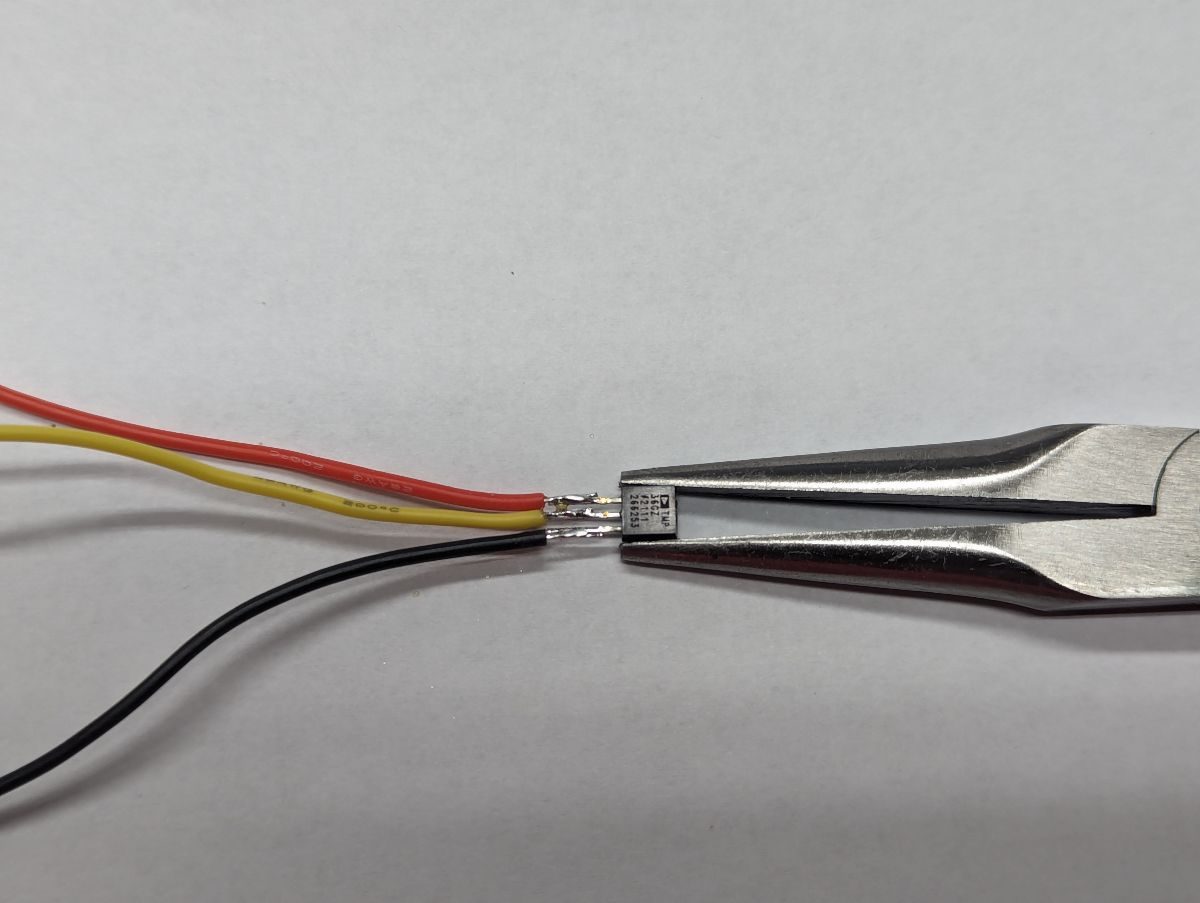
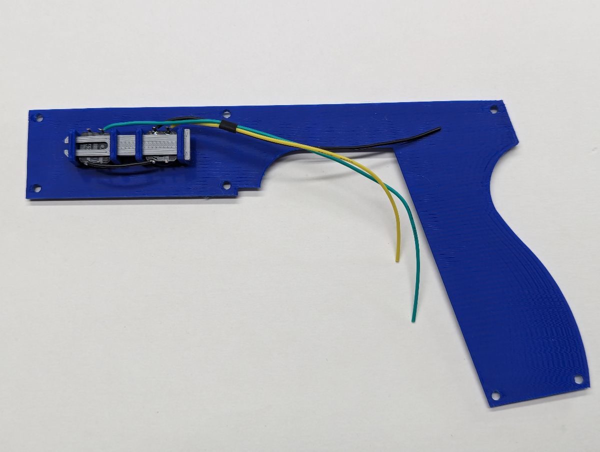
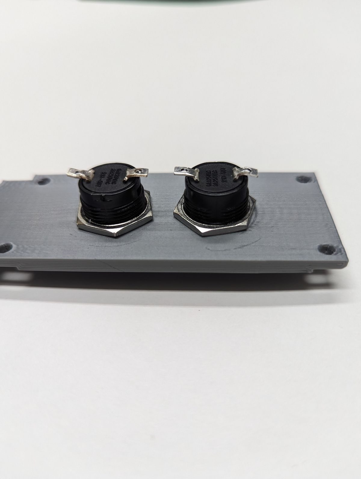
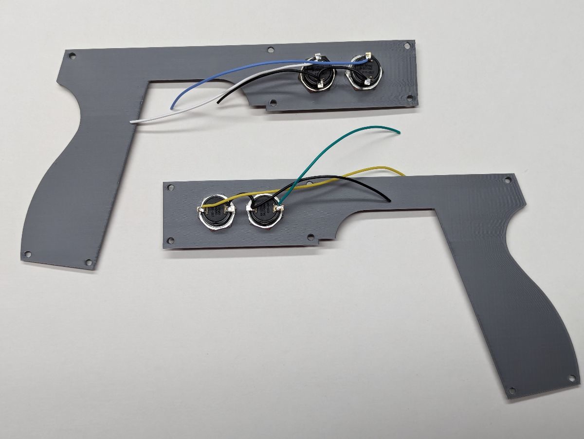
Cut half the length off each temperature sensor lead. Cut three wires, one red, one black and one another color. Strip and tin the ends of each wire. Tin the temperature sensor leads. Solder the wires as shown. Install heat shrink tubing over each solder connection, keep the tubing as close as possible to the body temperature sensor as you shrink the tubing. Solder the other end of the red wire to the Vcc distribution block, the black wire to the ground distribution block and the colored wire to the appropriate pin on your microcontroller. Before mounting the temperature sensor to the solenoid coil, test that it works properly (e.g. the Feedbacks screen on the Gun4IR GUI). Before plugging in the USB cable, make sure the ground and Vcc distribution blocks are not shorting against anything. Plug in the USB cable to the microcontroller and click on Get Temperature a few times and verify that it shows fairly consistent readings each time and the readings are close to ambient temperature. Use a heat source to warm the temperature sensor and verify that the measured temperature increases. Verify the measured temperature returns to ambient after a few minutes. Unplug the USB cable. Press the FLAT side of the temperature sensor onto the solenoid coil. Continue to press the bottom of the temperature sensor against the solenoid coil and place a spot of hot glue between the top of the temperature sensor and the solenoid coil. Hold until the glue hardens. Verify that the flat part of the temperature sensor body is making good contact with the solenoid coil and add more hot glue to hold the sensor in place. Wait, won’t the hot glue melt? Yes it will but if the temperature sensor does what it’s intended to do, the firmware will decrease or turn off power to the solenoid before reaching the melting temperature of hot glue.
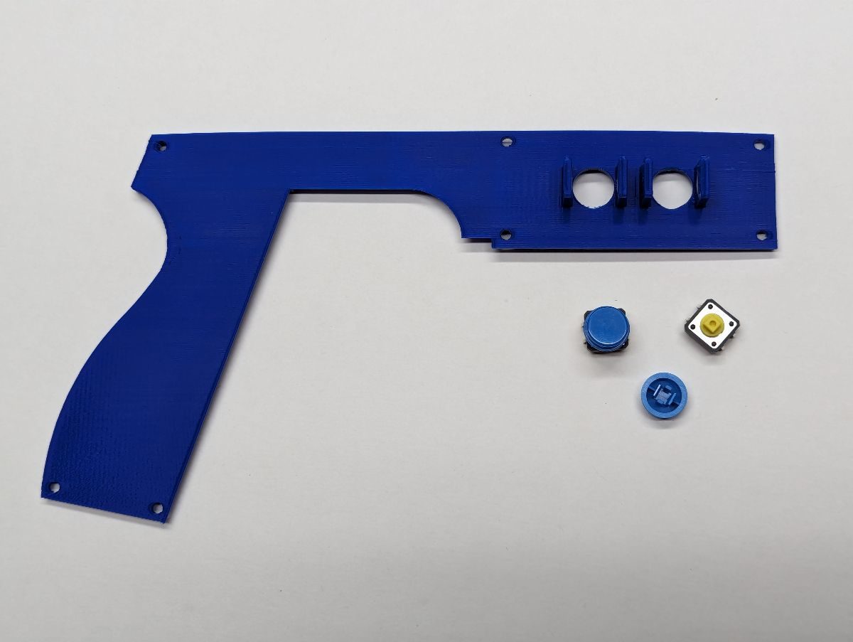
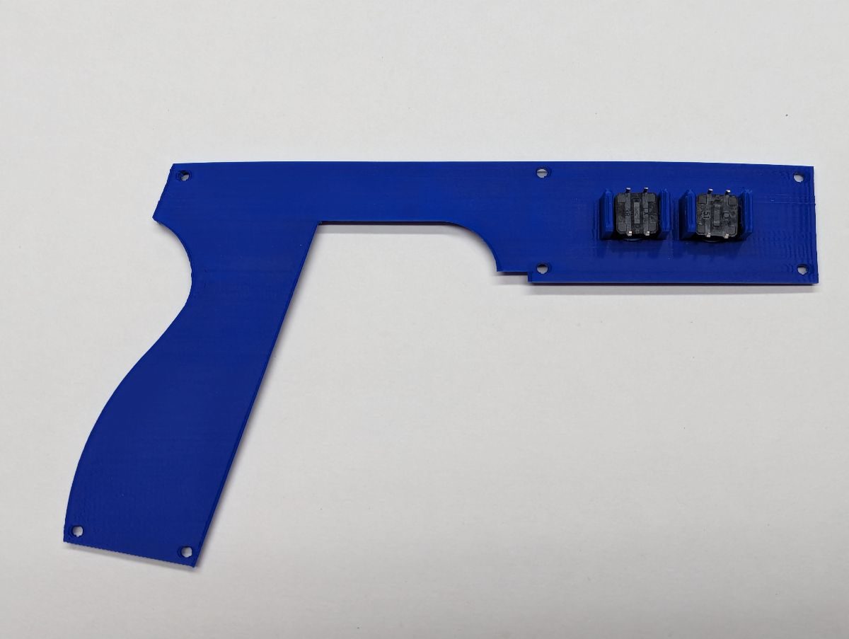
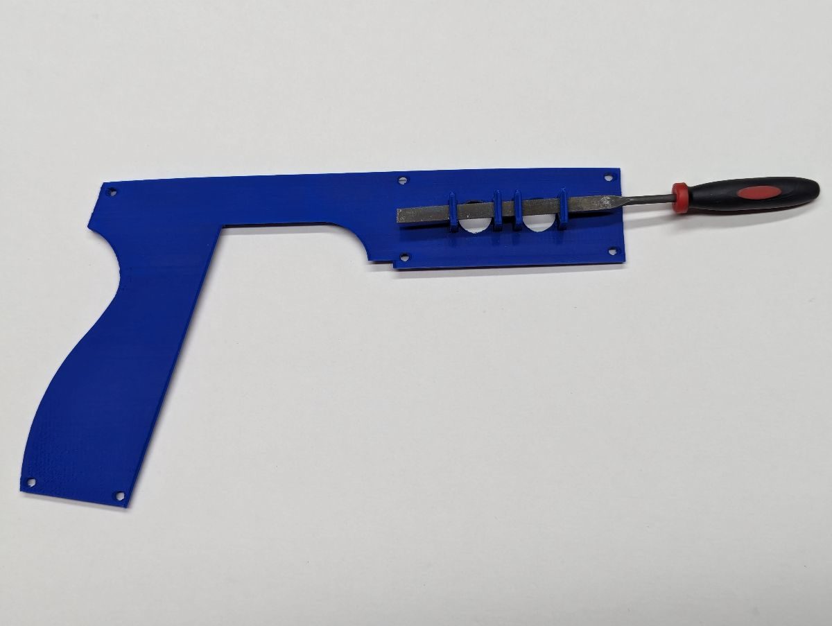
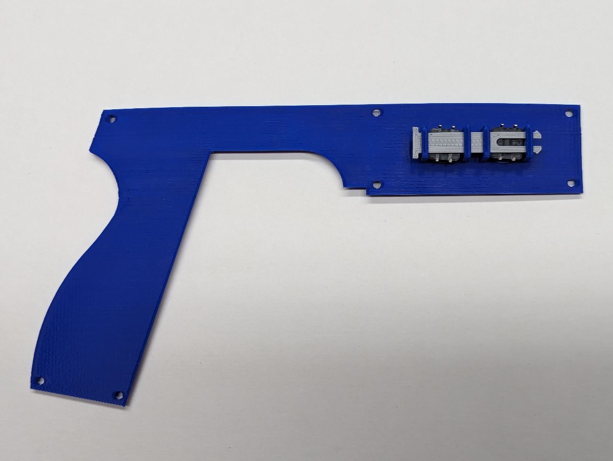
Install caps on the pushbuttons. Lay the pushbuttons into the side panel as shown. Insert the thicker Side Button Pin into the slot as shown. Push down on the back of each pushbutton as you insert the pin. Once the pin is fully inserted, test the action of each pushbutton to verify they operate properly. They should be slightly loose. If one or both pushbuttons does not “click” when pressed, remove the pin and pushbuttons and use a flat needle file to file any filament bumps along the edges of the rectangular hole. Reinstall the pushbuttons and pin and retest. If they still do not operate properly, use the thinner pin. Daisy chain a ground wire to both pushbuttons, leaving a short length to solder to your ground distribution block. Solder wires to the remaining terminals. Install one Side Panel to the Frame, the other side panel will be installed later. Solder the ground wire to the ground distribution block. Solder the two colored wires to their appropriate microcontroller input pins. You may want to make the wires on one side extra long so that it can be moved out of the way when you open your lightgun to work on it.
Install caps on the pushbuttons. Lay the pushbuttons into the side panel as shown. Insert the thicker Side Button Pin into the slot as shown. Push down on the back of each pushbutton as you insert the pin. Once the pin is fully inserted, test the action of each pushbutton to verify they operate properly. They should be slightly loose. If one or both pushbuttons does not “click” when pressed, remove the pin and pushbuttons and use a flat needle file to file any filament bumps along the edges of the rectangular hole. Reinstall the pushbuttons and pin and retest. If they still do not operate properly, use the thinner pin. Daisy chain a ground wire to both pushbuttons, leaving a short length to solder to your ground distribution block. Solder wires to the remaining terminals. Install one Side Panel to the Frame, the other side panel will be installed later. Solder the ground wire to the ground distribution block. Solder the two colored wires to their appropriate microcontroller input pins. You may want to make the wires on one side extra long so that it can be moved out of the way when you open your lightgun to work on it.
Insert 2 16mm pushbuttons in each side panel. Note that there are flat sides that will only allow the pushbuttons to be installed a certain way. Use the supplied nut to secure the buttons to the side panel. Use a needle nose pliers to start to bend the switch terminals as shown. Use the side of the pliers to push the terminals to a 90 degree angle as shown. Daisy chain a ground wire to both pushbuttons, leaving a short length to solder to your ground distribution block. Solder wires to the remaining terminals. Install one Side Panel to the Frame, the other side panel will be installed later. Solder the ground wire to the ground distribution block. Solder the two colored wires to their appropriate microcontroller input pins.
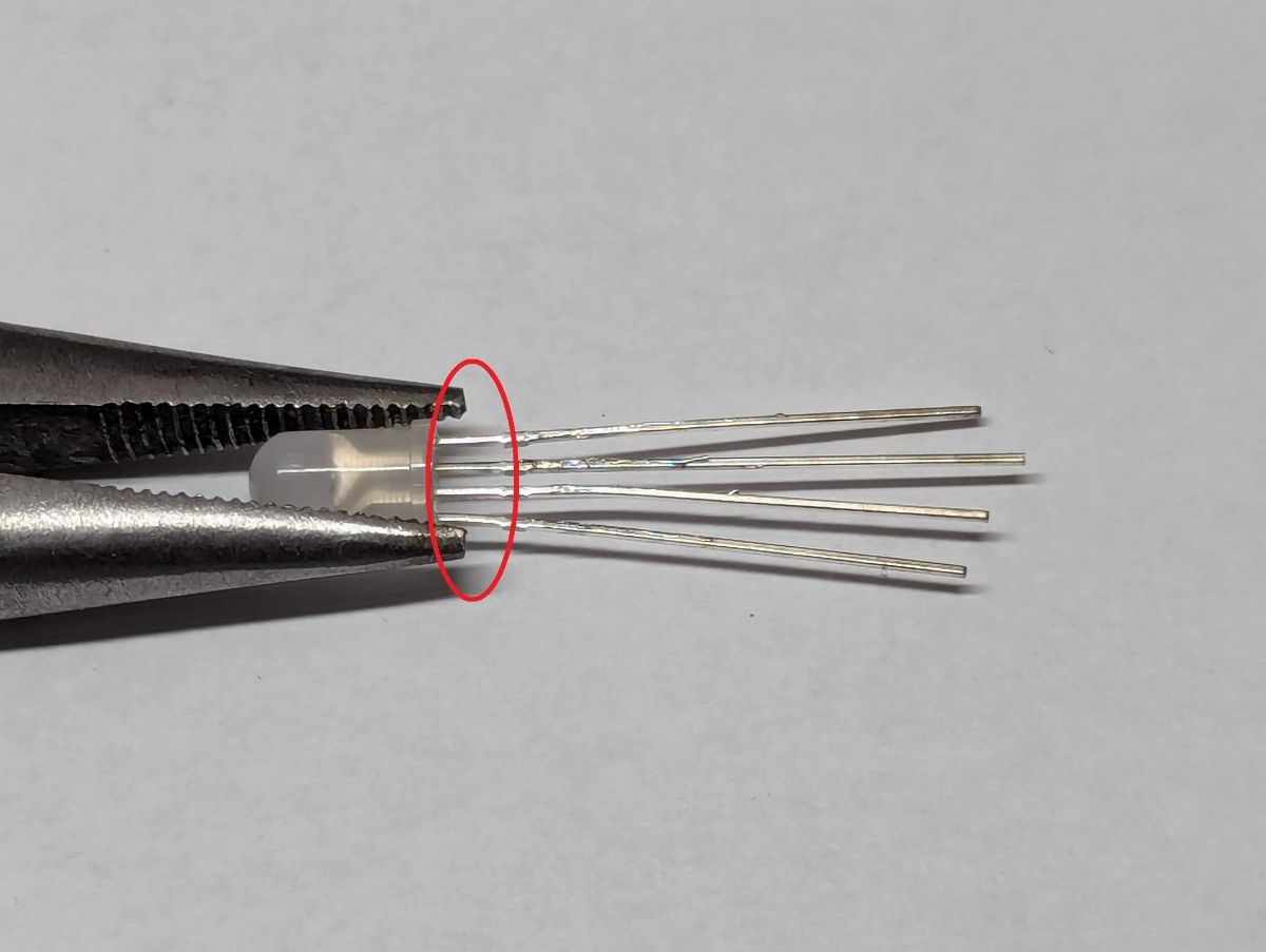
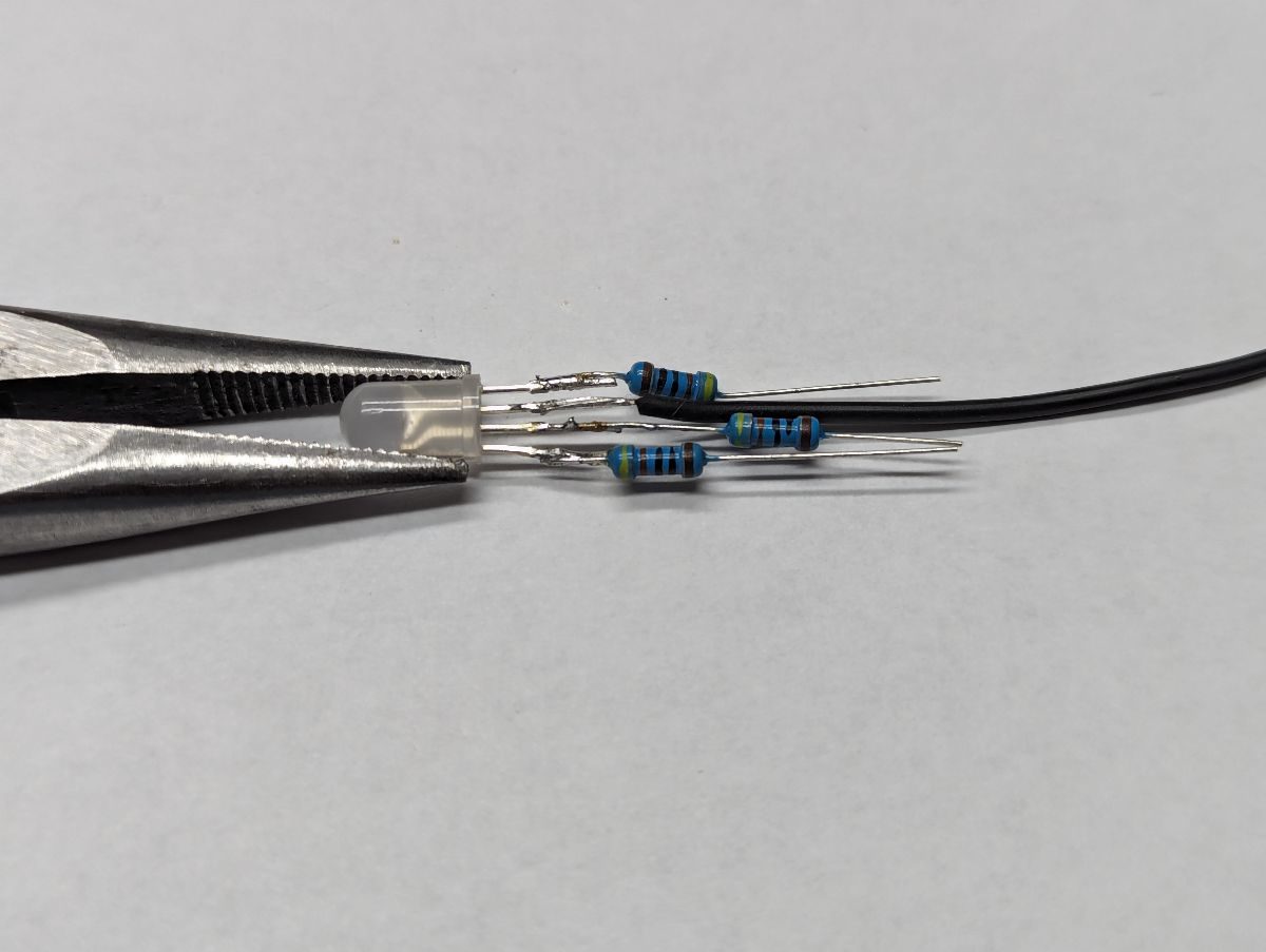
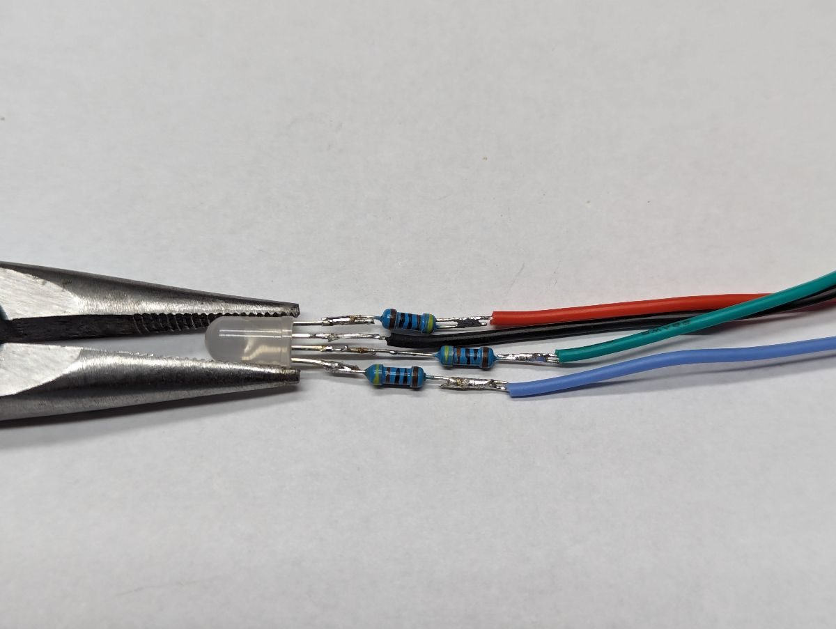
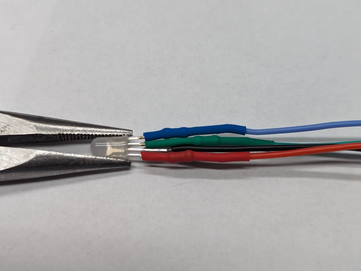
If you are installing an RGB LED in the back of your lightgun. IMPORTANT: do not solder in the area circled in red. Tinning the RGB leads and wires before soldering them together makes the process easier. Trim the longest RGB LED lead and solder a black wire to it. Trim the other leads and solder current limiting resistors to each (exact resistance does not matter, 300 to 500 ohms will give good brightness without drawing too much current). Solder colored wires to each resistor. Slide heat shrink tubing over each resistor but do not cover the area circled in red. Shrink the tubing.
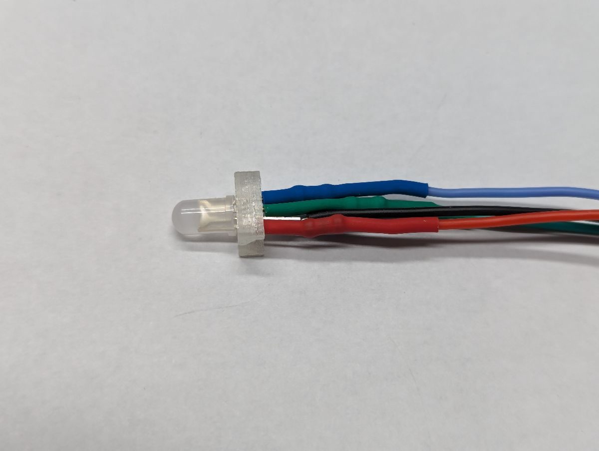
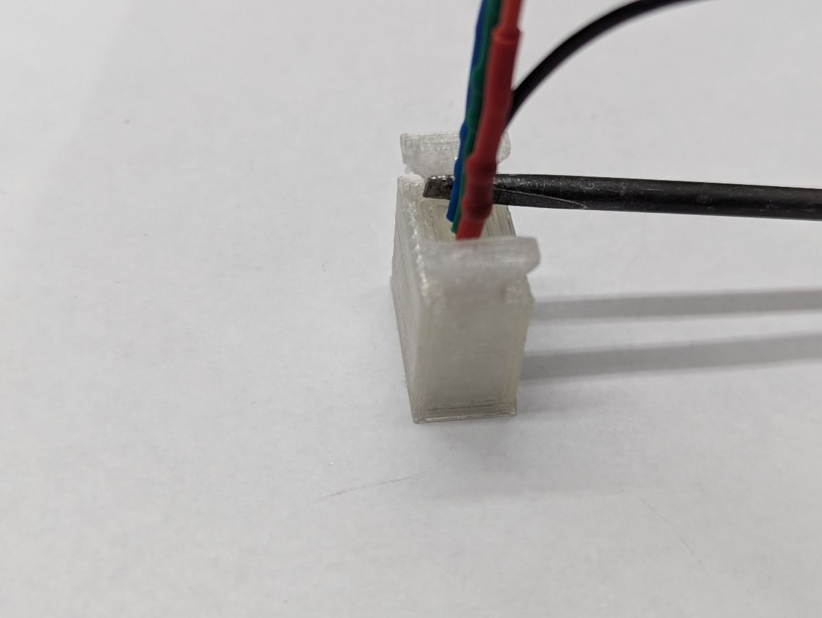
Slide the RGB Spacer between the bottom of the LED and the heat shrink tubing. Push the RGB LED and Spacer into the RGB Mount. Use a small screwdriver to push the Spacer flush to the Mount. Feed the wires through the hole in the back of the Frame and insert the RGB Mount fully into the Frame. Slide the Back Clip over the RGB Mount. Solder the colored wires to the appropriate microcontroller pins. Solder the black wire to a ground distribution block.
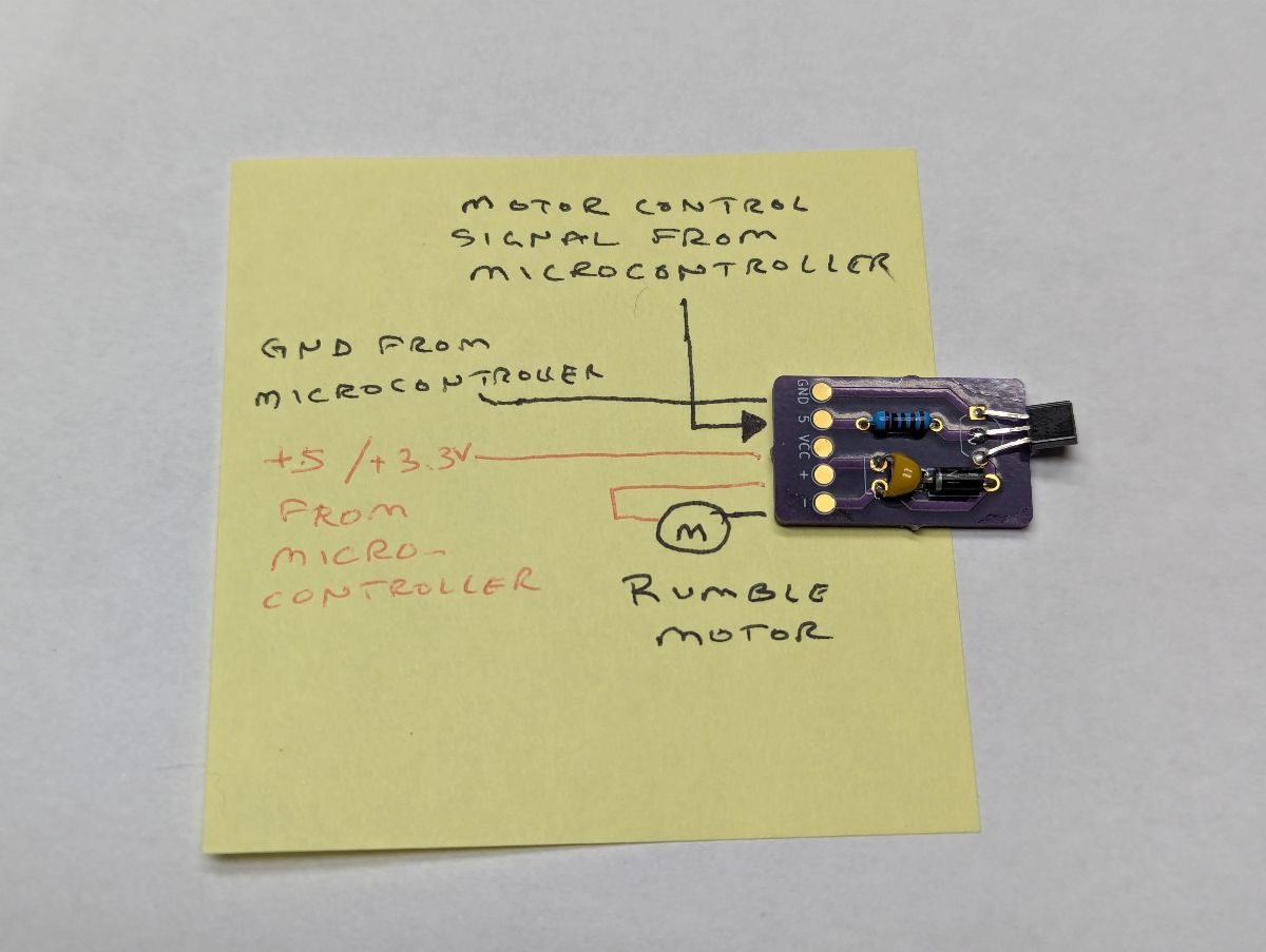
Tin the solder pads on the rumble motor driver PCB (obtained from OSHPark). Strip and tin the motor wires and attach them to the PCB. Solder a ground wire between the PCB and a ground distribution block. Solder a wire between the PCB and a Vcc distribution block. Solder a wire between the PCB and the rumble motor control pin on the microcontroller. Verify that the rumble motor works. Secure the wires going to the PCB with a zip tie. Place heat shrink tubing over the entire rumble motor driver PCB.
Tin the solder pads on the rumble motor driver PCB (obtained from OSHPark). Strip and tin the motor wires and attach them to the PCB. Solder a ground wire between the PCB and a ground distribution block. Solder a wire between the PCB and a Vcc distribution block. Solder a wire between the PCB and the rumble motor control pin on the microcontroller. Verify that the rumble motor works. Secure the wires going to the PCB with a zip tie. Place heat shrink tubing over the entire rumble motor driver PCB.
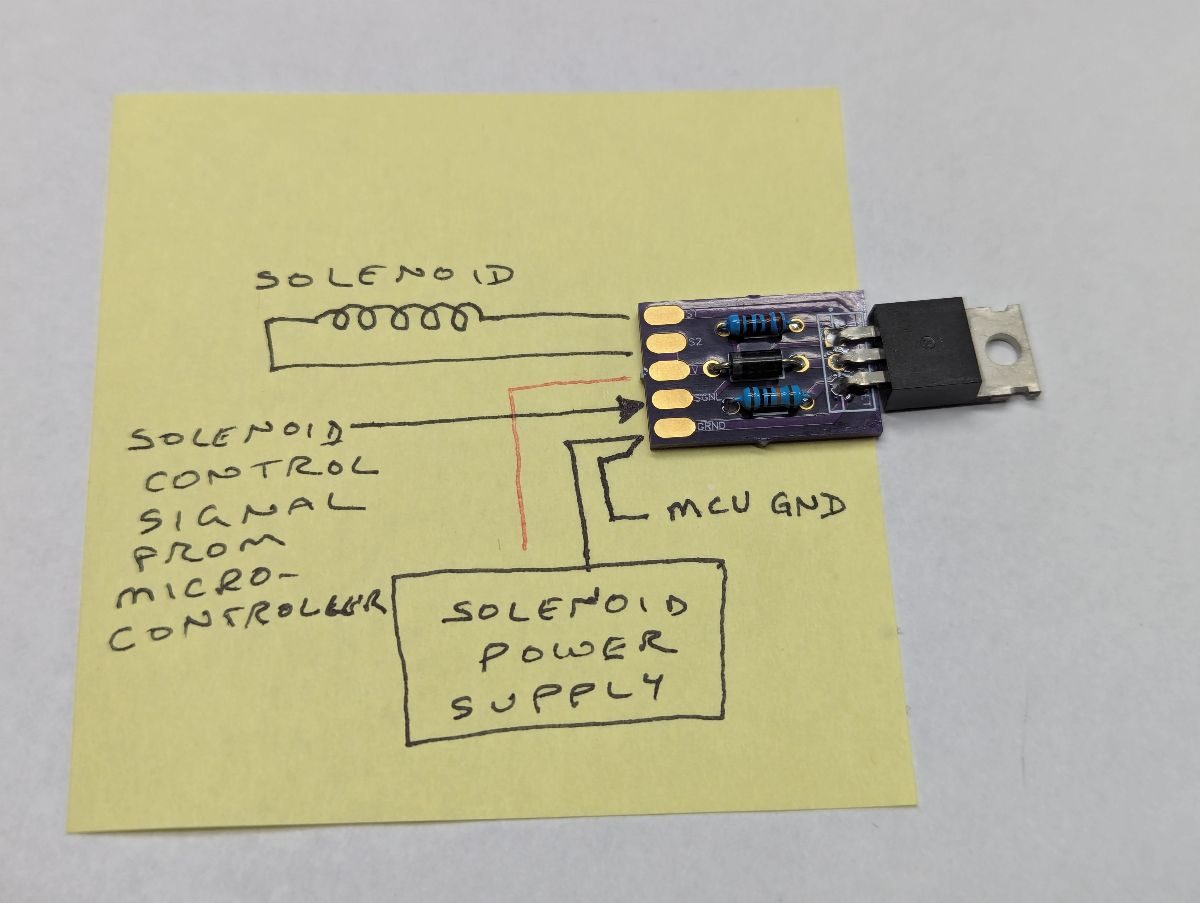
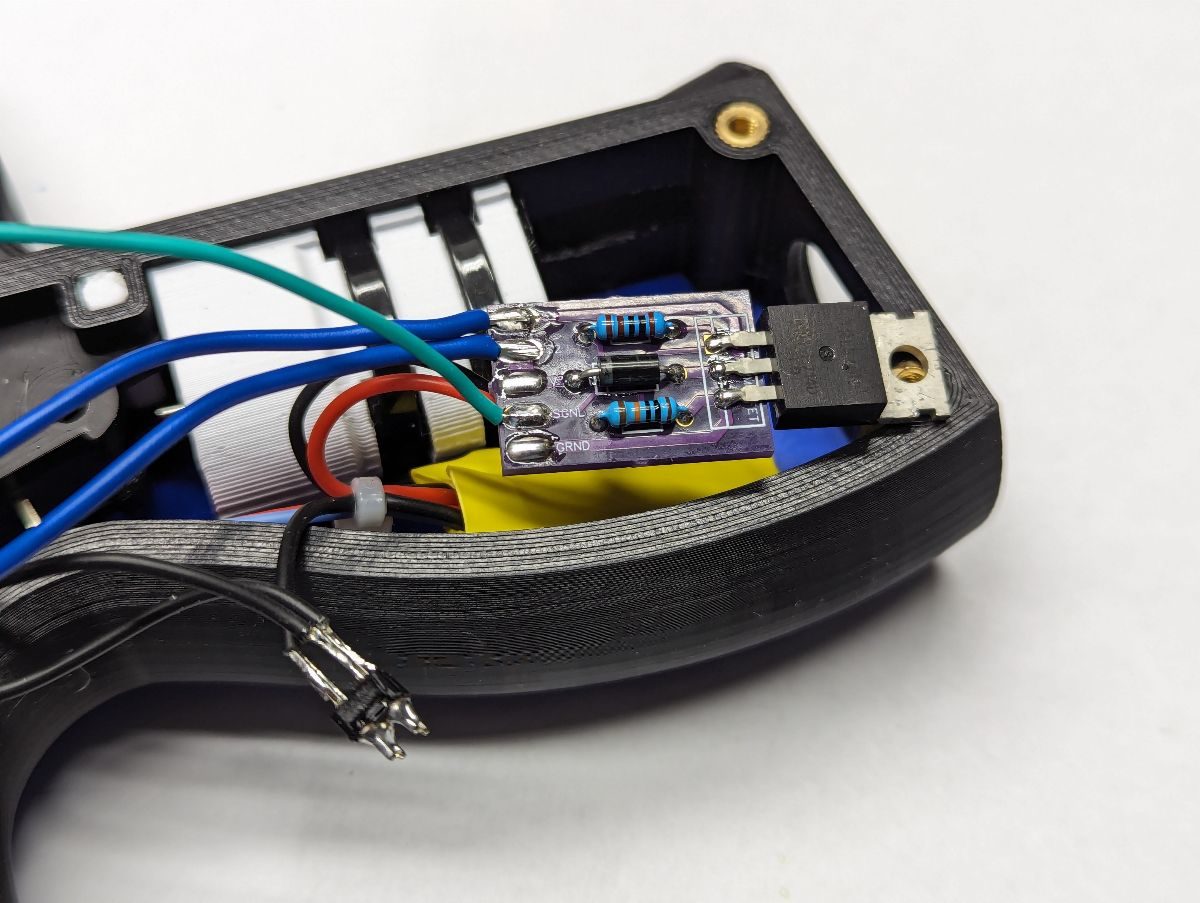
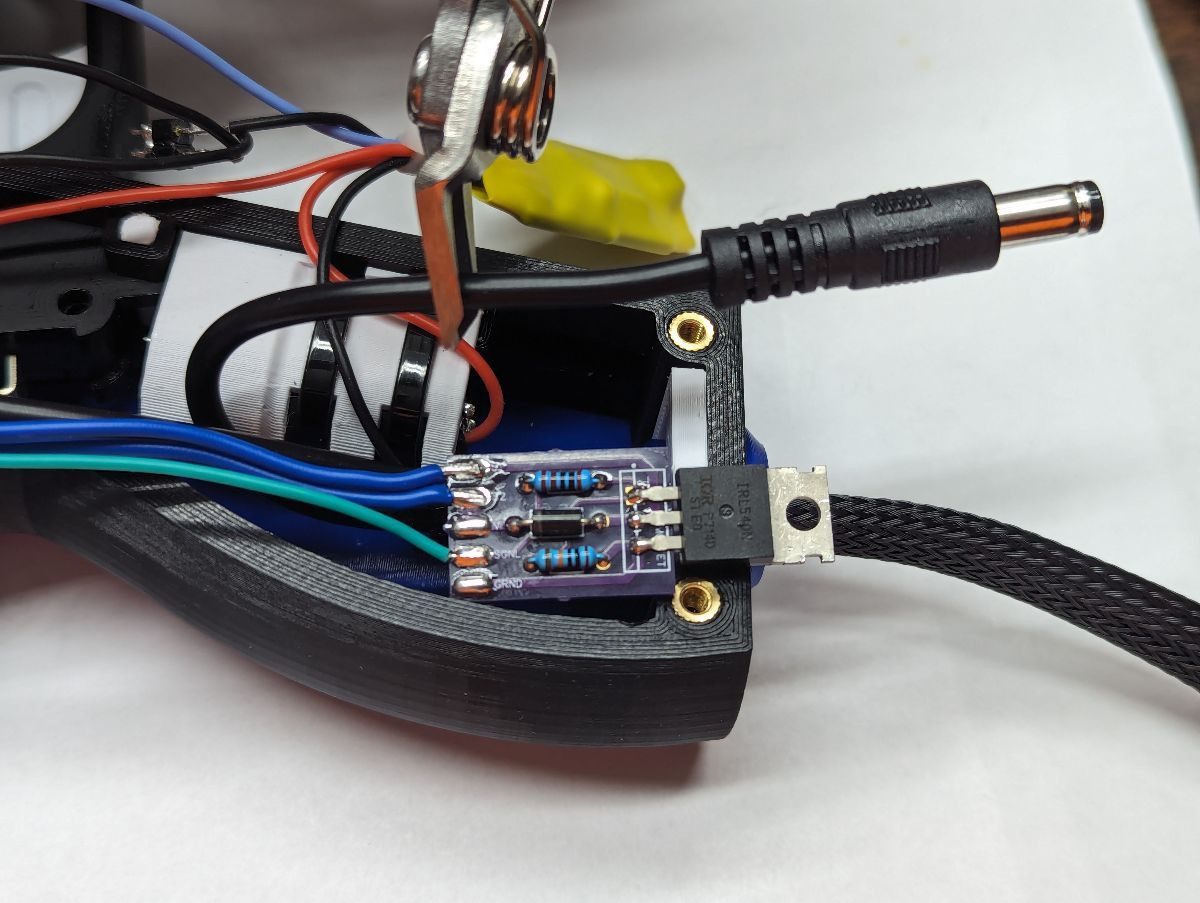
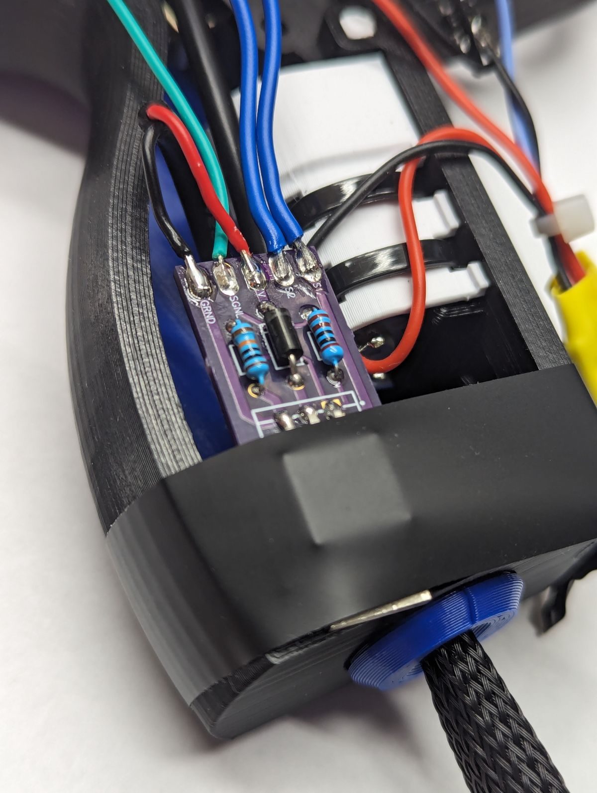
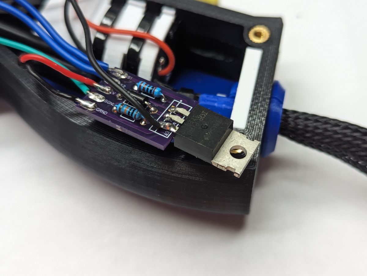
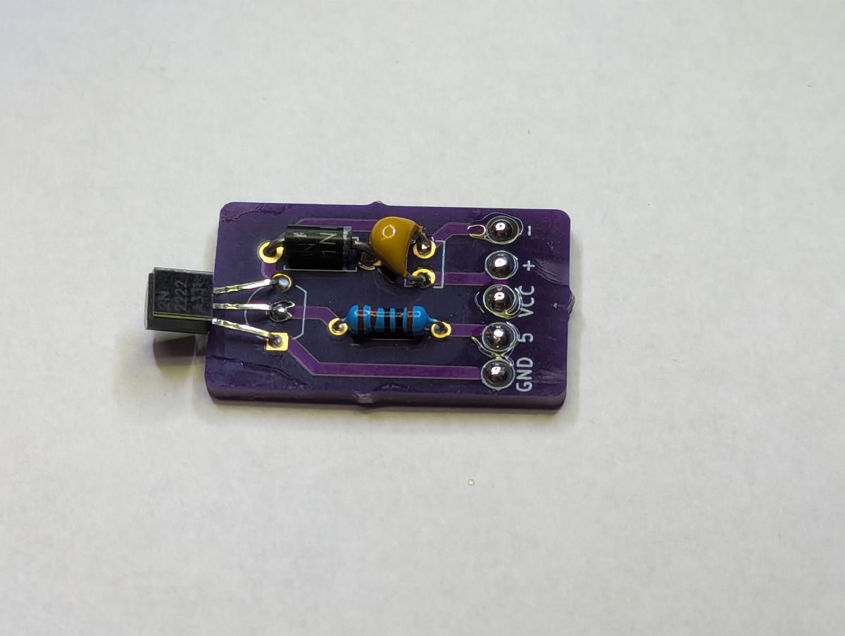
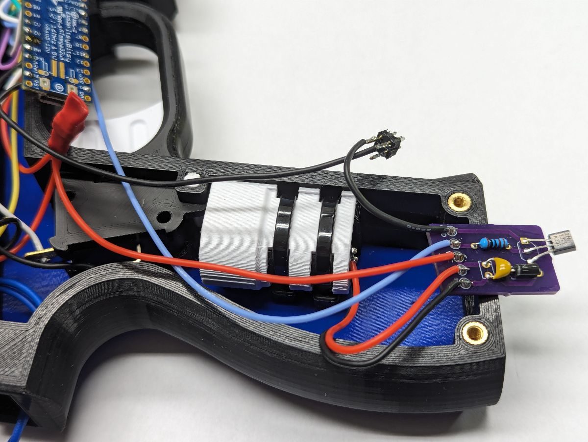
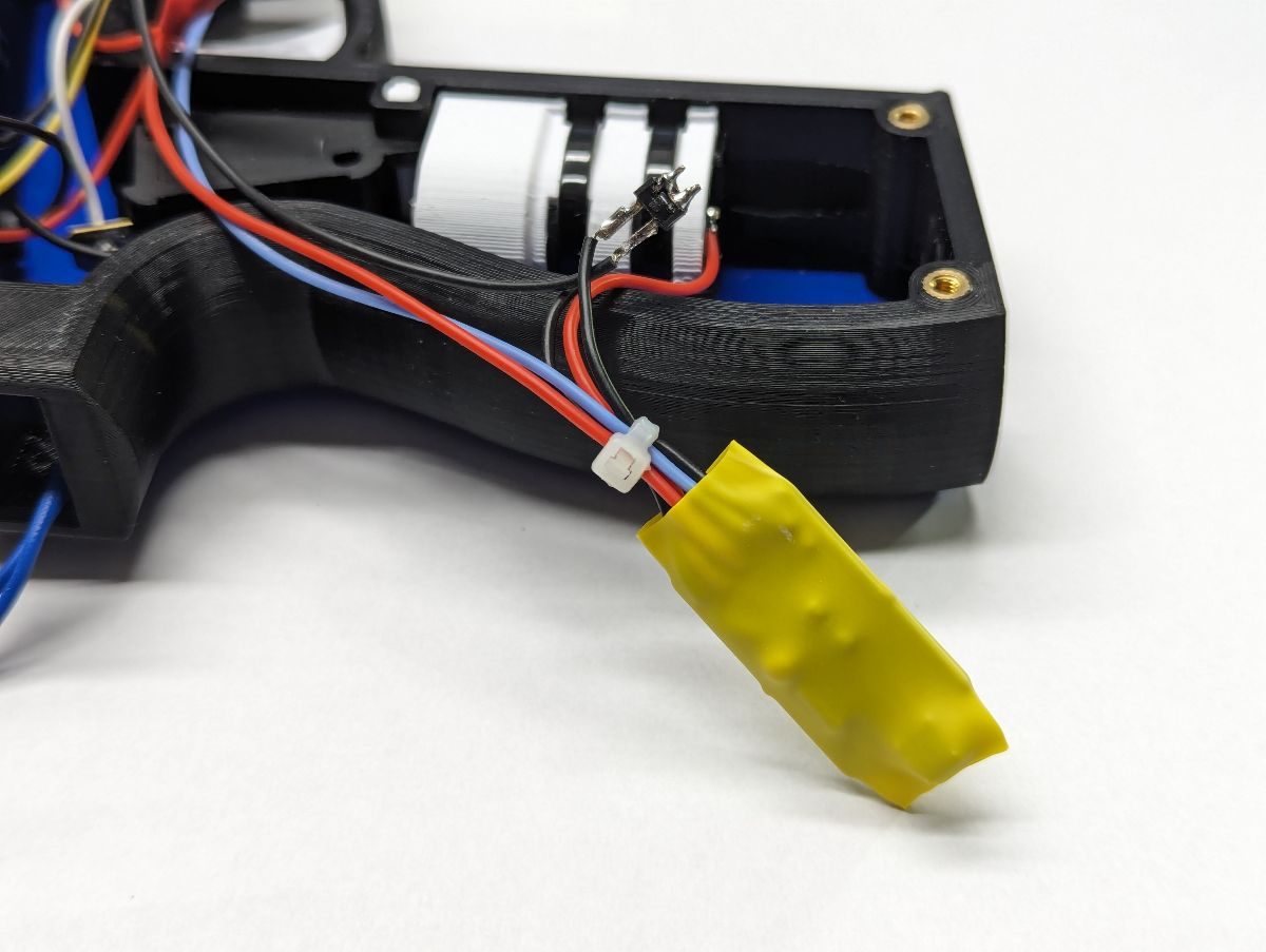
Tin the solder pads on the solenoid driver PCB (obtained from OSHPark). Strip and tin the solenoid wires and solder to the PCB. Solenoids do not have polarity so it does not matter which pad (S1 or S2) you solder solenoid wires to. Solder a wire between the SGNL pad on the PCB and the solenoid control pin on the microcontroller. Solder the + solenoid power wire to the the V pad on the PCB and the – solenoid power wire to the GRND pad of the PCB. Unfortunately, this PCB does not have an extra ground solder pad to connect the microcontroller ground to the solenoid driver ground. Instead, solder a wire between the ground distribution block and the right leg of the MOSFET as shown. Verify the solenoid driver works (e.g. Gun4IR GUI). Place heat shrink tubing over the entire solenoid motor driver PCB.
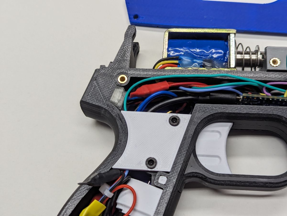
Remove the side panel that was attached earlier. Carefully push wires in the grip around the trigger switch. Insert (2) M3x20 screws into the Frame Brace. Insert the screws through the trigger switch and fasten the screws with washers and nuts (or M3 nuts with nylon inserts).
Attach each side panel with (7) M3x8 screws being careful not to pinch any wires. The Side Panels should lay flush to the Frame without any force. If there is any resistance, adjust the location of the wires and distribution blocks so they do not interfere. A zip tie cutoff is useful for pushing any stray wires back inside the Frame.
Use the Camera Test feature of the Gun4IR GUI to test each button, trigger, pedal/pump, RGB LED, temperature sensor, rumble motor and solenoid. Note that the Trigger input will not be recognized if the camera is not pointing at the IR LEDs. Adjust the solenoid and rumble motor timings as needed. Enable the temperature sensor checkbox. Be sure to upload your settings to the lightgun when you are finished making changes.