IR LED Mount Build Guide
Added by iCON on February 24, 2023iCON
Say thanks by giving iCON a tip! Why?
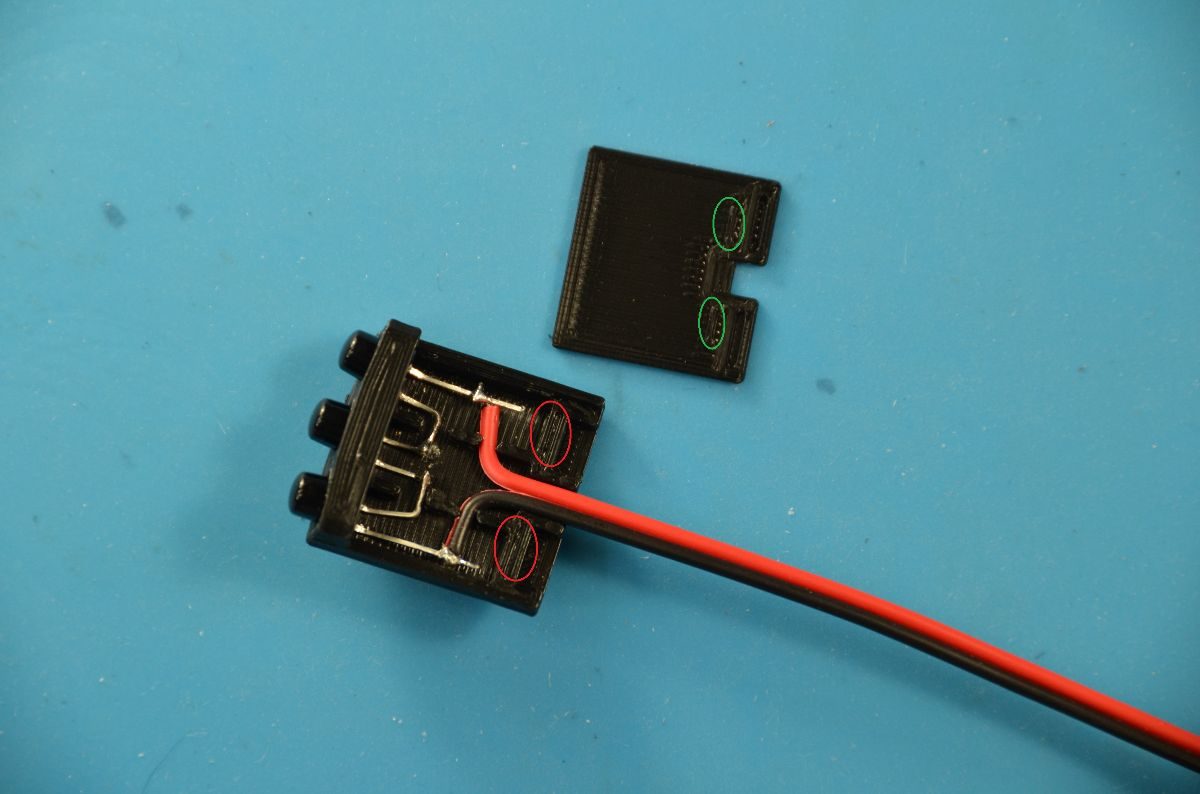
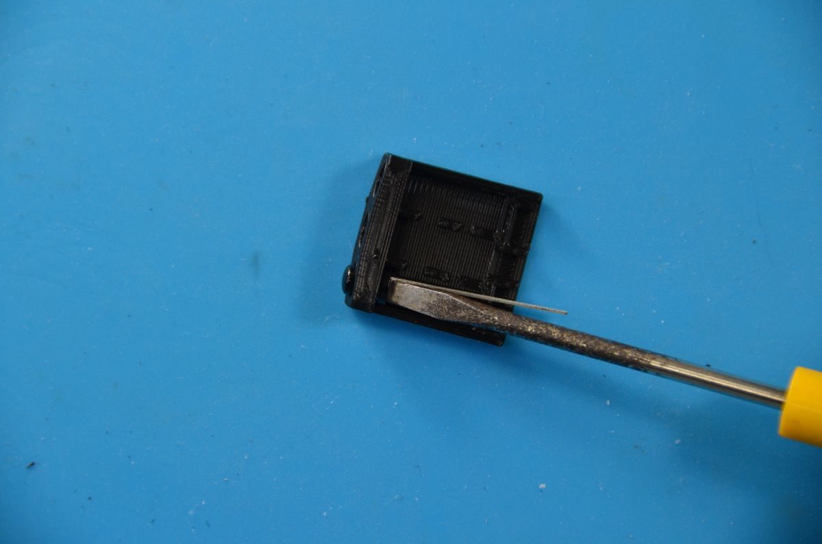
Before building the IR LED assembly, it’s a good idea to test fit the Cover onto the Base. There are two nubs on the bottom of the Cover (circled in green) that snap fit into slots on the Base (circled in red). The cover should slide onto the base with reasonable effort and should not need to be forced on. If you struggling to slide the Cover onto the Base, use calipers to verify that the cover is 1.2mm thick. If your Cover is thinner than that, your print head may be too close to the bed. If so, adjust your bed leveling. The Cover should snap onto the base. To remove the Cover, insert a flat head screwdriver between the center LED and the cover and pry the cover towards the back to release the snap fit then slide the cover off.

Test fit the IR LEDs by temporarily inserting them into the front of the Base. The fit should be tight but not require tools to force the LED into the base. If the fit is too tight, use and X-ACTO knife, small round file, or rolled up sandpaper to enlarge the hole. If you have a metric drill bit set, use a 5.0mm drill bit for generic clear IR LEDs or a 4.8mm drill bit for the black OSRAM IR LEDs. Do not make the hole too large to avoid having to use superglue to hold the LED in. Repeat this process for each LED hole.
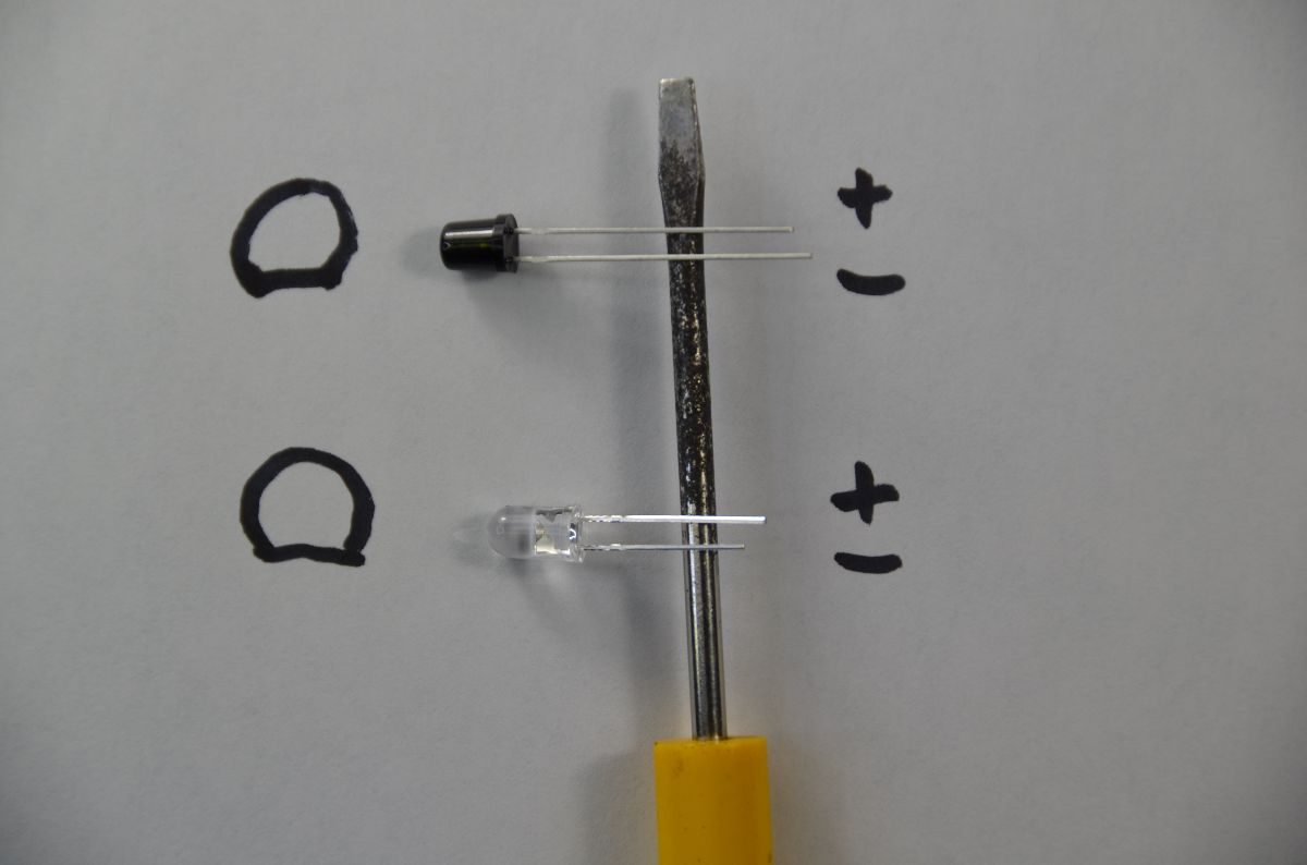
- The long lead of the black OSRAM SFH 4547 infrared LEDs is NEGATIVE, the short lead is POSITIVE.
- The long lead of most every other LED ever made is the POSITIVE lead, the short lead is NEGATIVE.
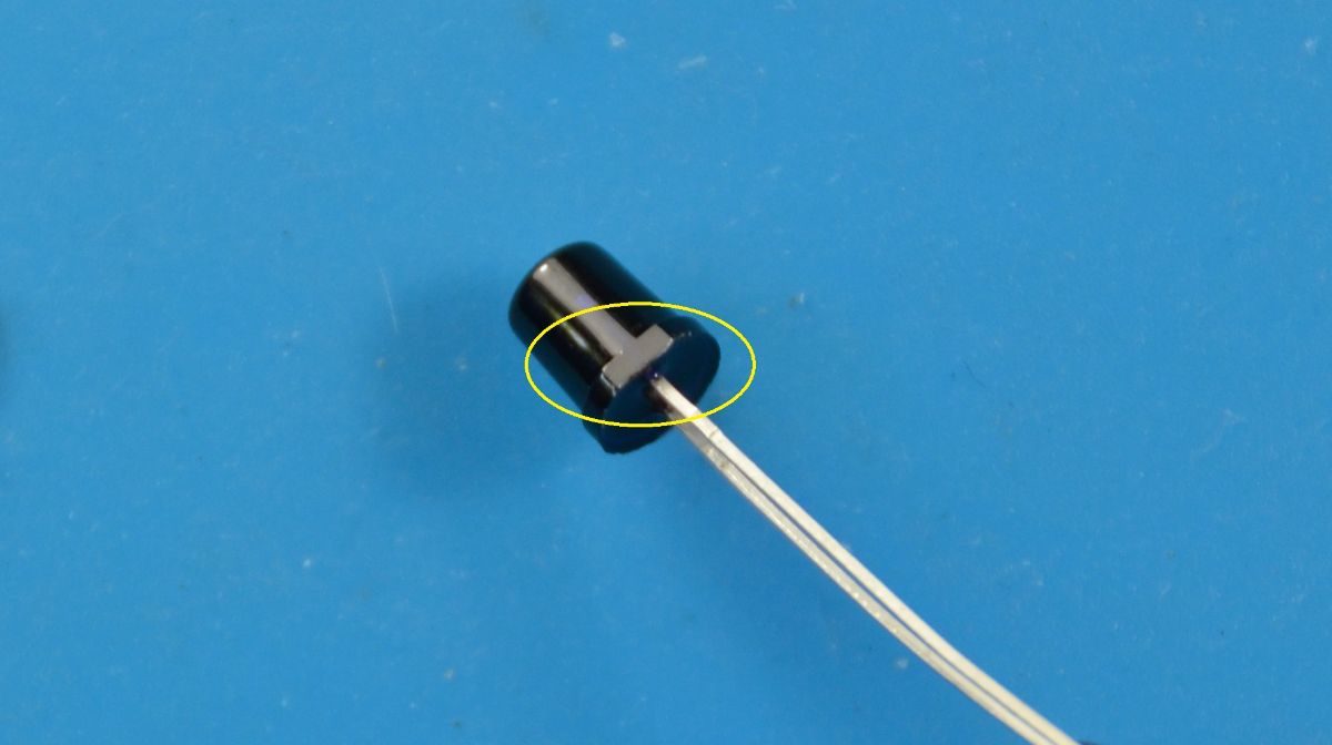
- Instead of using lead length to identify polarity, look for the flat area on the rim (circled in yellow) to identify the negative lead.


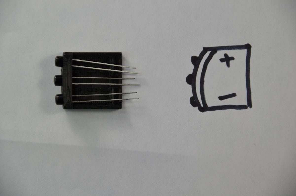

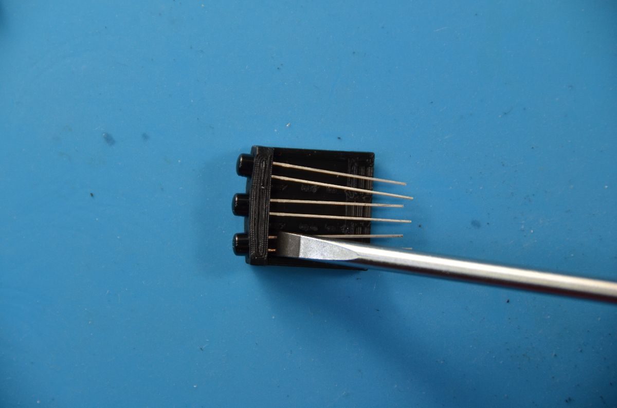
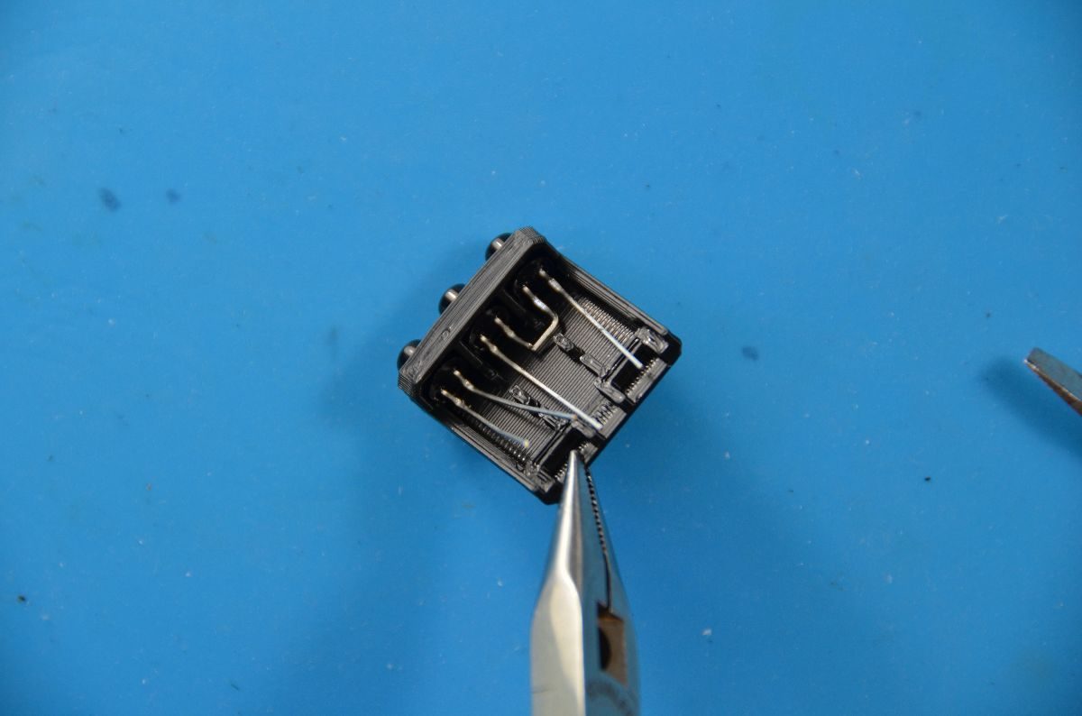
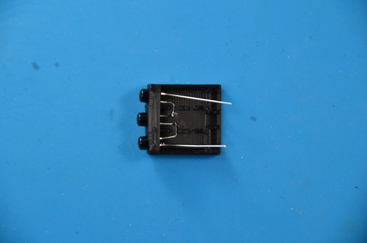
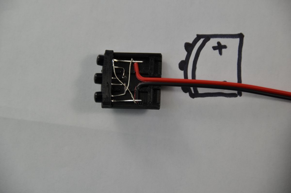
Lay the infrared LED onto the Base so the leads are parallel to the Base. Use a 5-6mm wide flat head screwdriver to gently push the infrared LEDs all the way into the Base. Insert each LED the same way, either with the long lead on top or the long lead on the bottom. Make a drawing so you can remember the polarity. The LEDs should fit snug enough to stay in place without glue but if the LEDs are too loose, you may want to add a drop of superglue where the pencil is pointing to hold them in place. You may want to verify that your LEDs are working before you glue them.
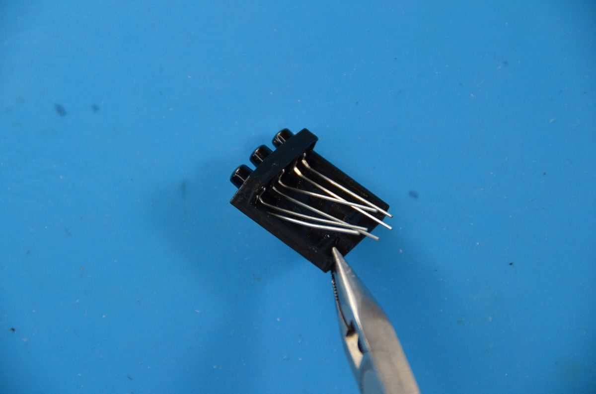
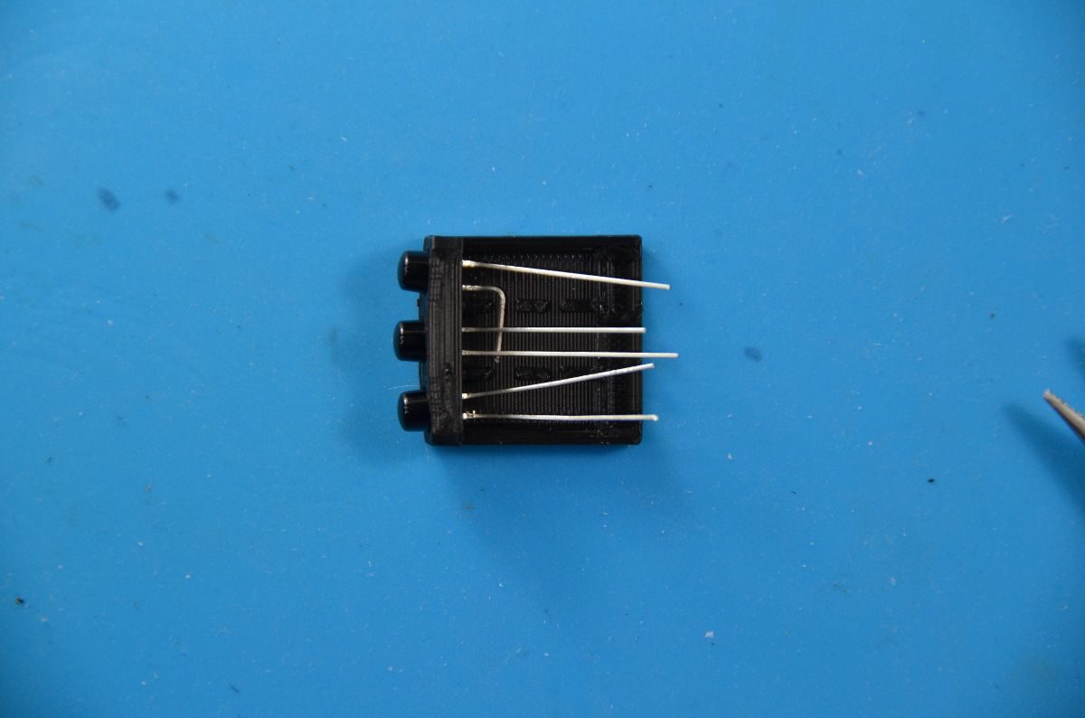

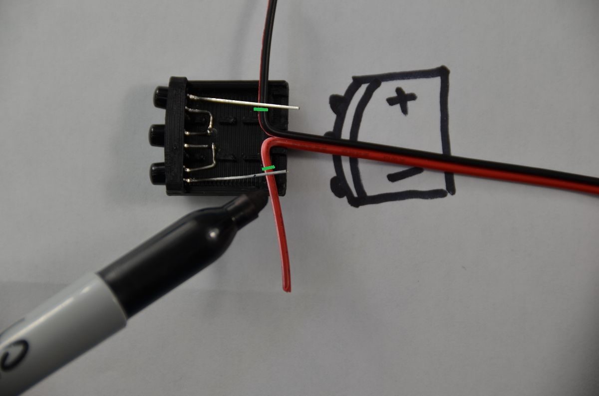
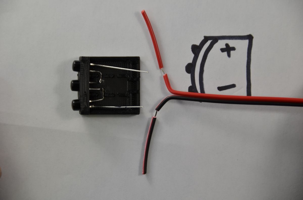
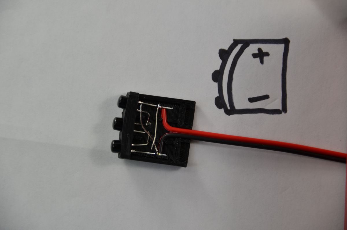
Cut an appropriate length of 22 AWG wire, split one end of the wire and bend into 90 degree angles as shown. Slide the wire under the two outer LED leads so it lines up with the channels in the Base. Mark the wires at the green lines and strip the wire at the marks you just made. If you strip the wire slightly you can twist and pull the insulation off the wires to keep the wire stands from fraying. Reform your wires into 90 degree angles and reinsert the wire beneath the LED leads. Refer to the drawing you made earlier to make sure your polarity is correct. Bend the bare wires over the LED leads, solder and trim the excess leads and wire. Make sure the solder joints are not too large to prevent the Cover from sliding onto the Base.

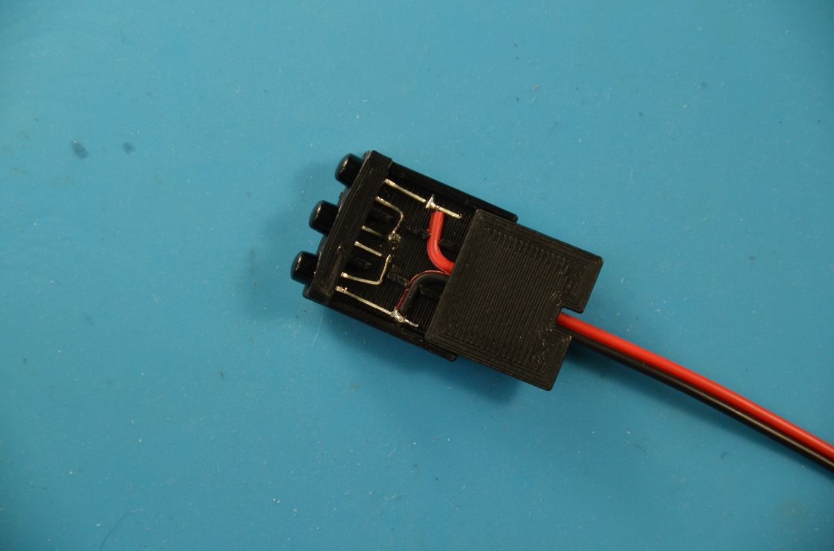
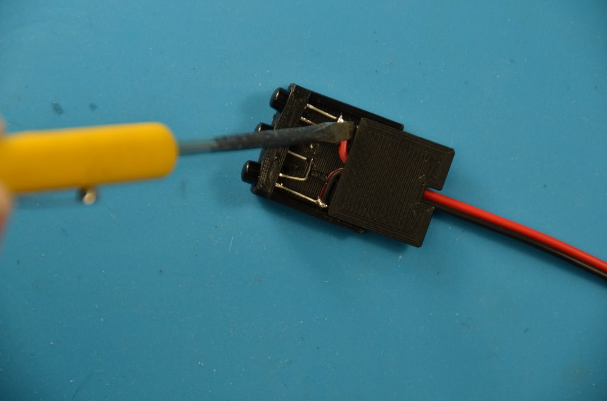
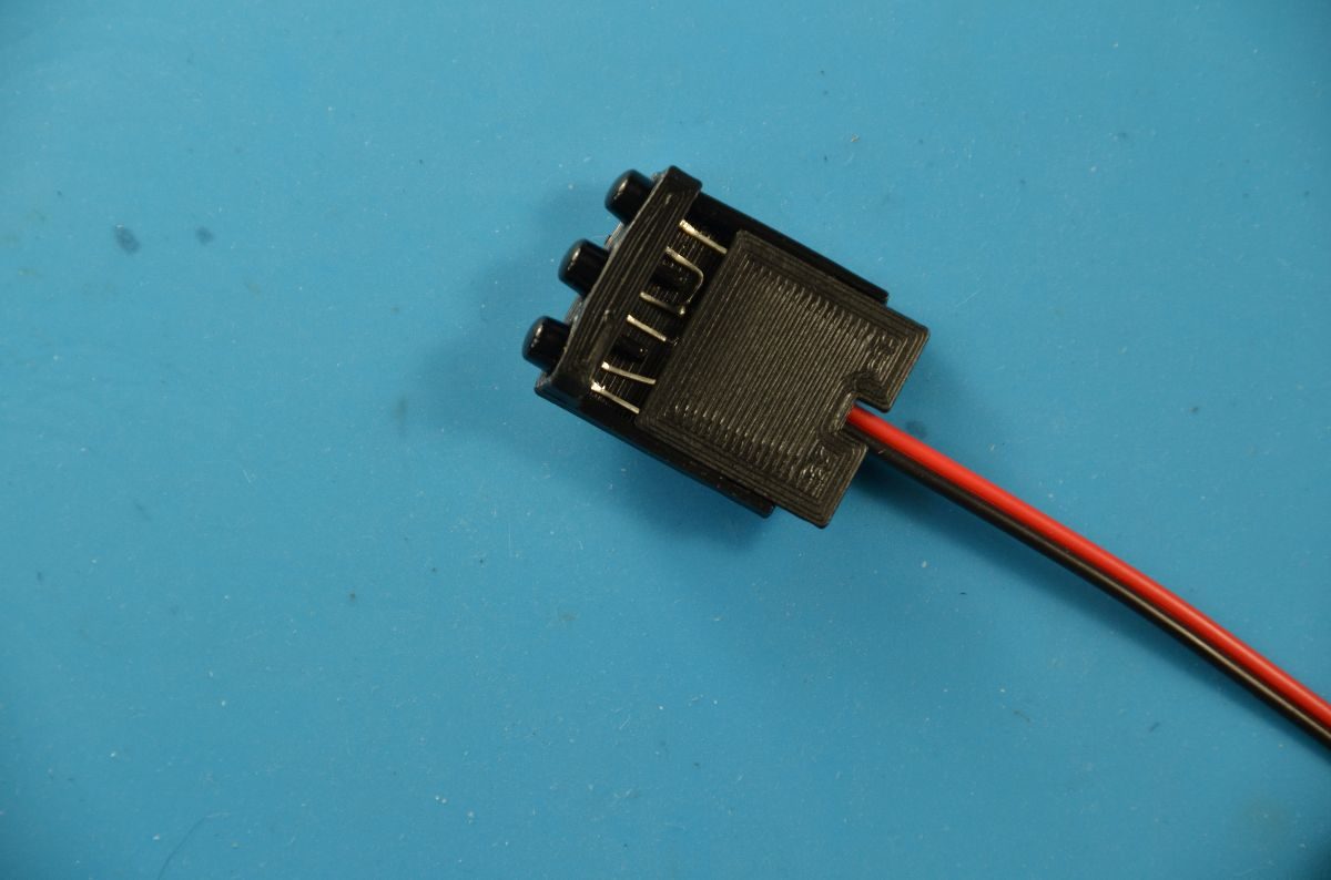

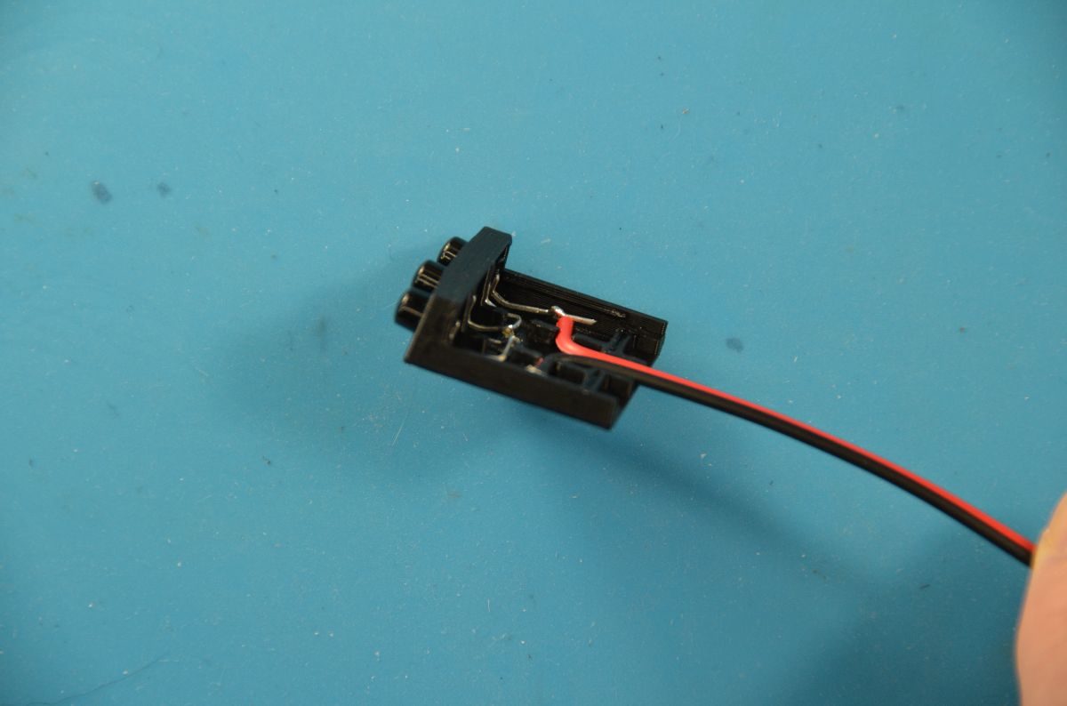
Two nubs on the Cover (circled in green) snap fit into slots on the Base (circled in red). Lay the Cover nub side down onto the Base. Slowly push the cover onto the base. If the solder joints or leads interfere with the cover sliding on, use a small flat head screwdriver to push the wire/lead/solder joint down while continuing to push the Cover onto the Base. The Cover should snap into place once fully installed. Remember to add the appropriate current limiting resistor before testing your IR LED assembly.