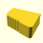
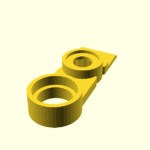
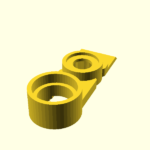
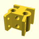
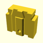
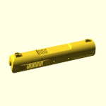
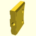
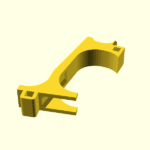
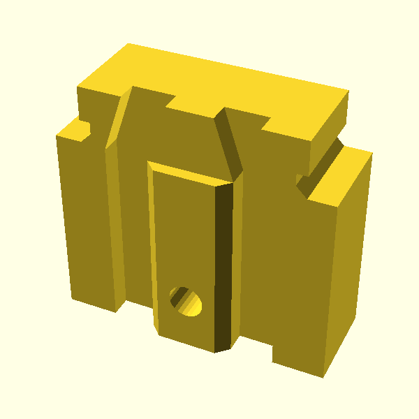
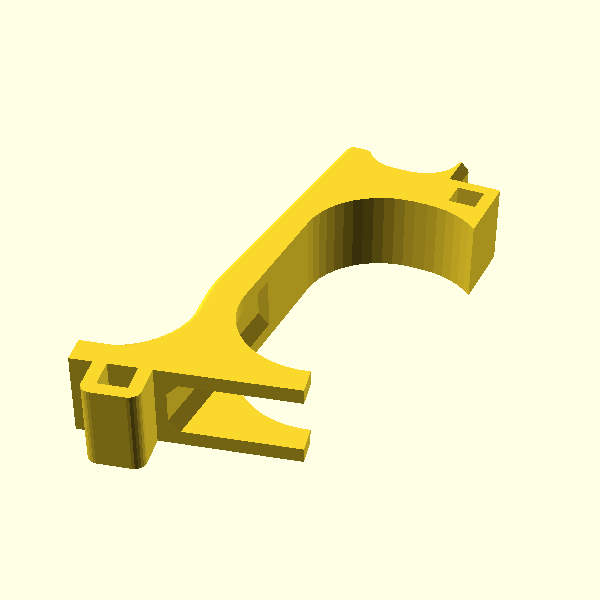
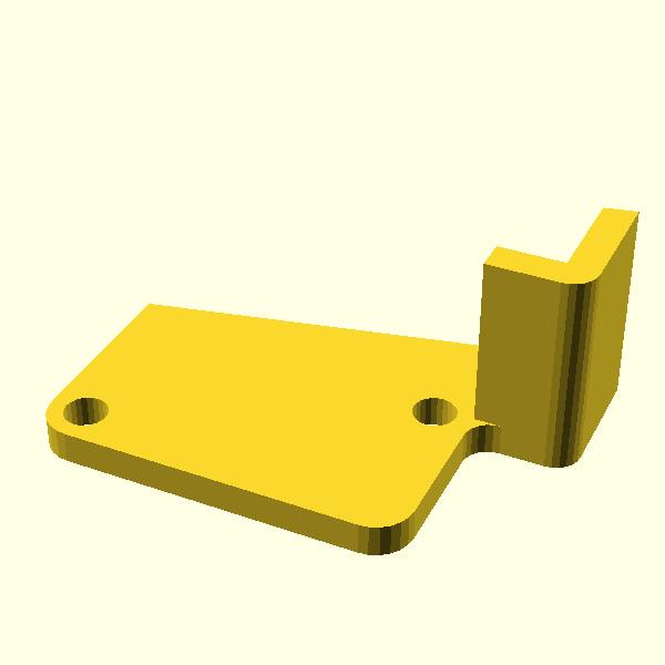
iCON1

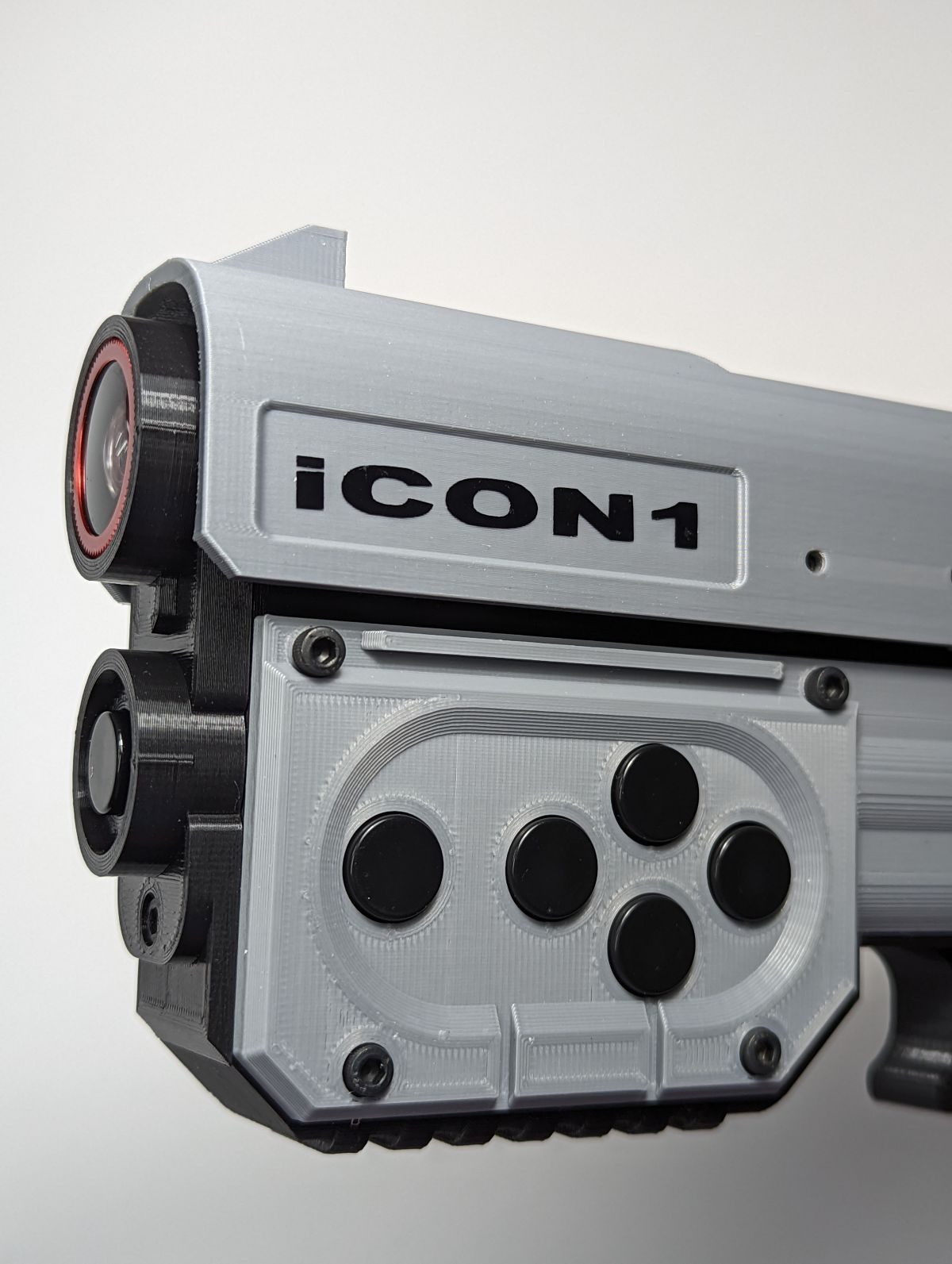
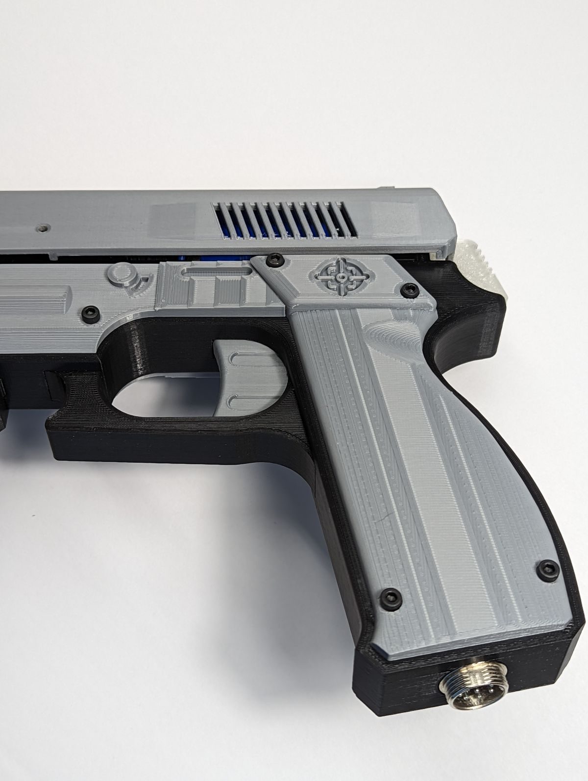
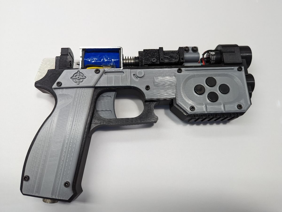
3D Printed Lightgun by iCON

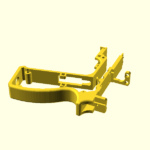
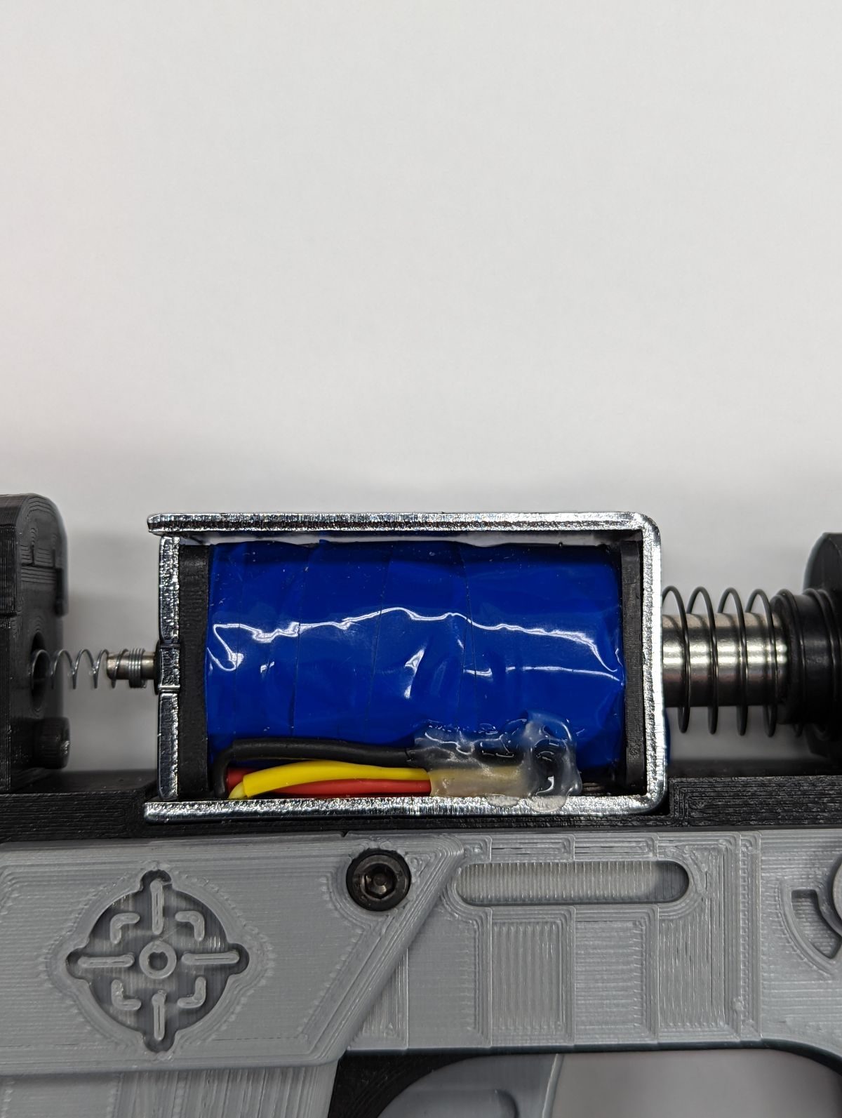
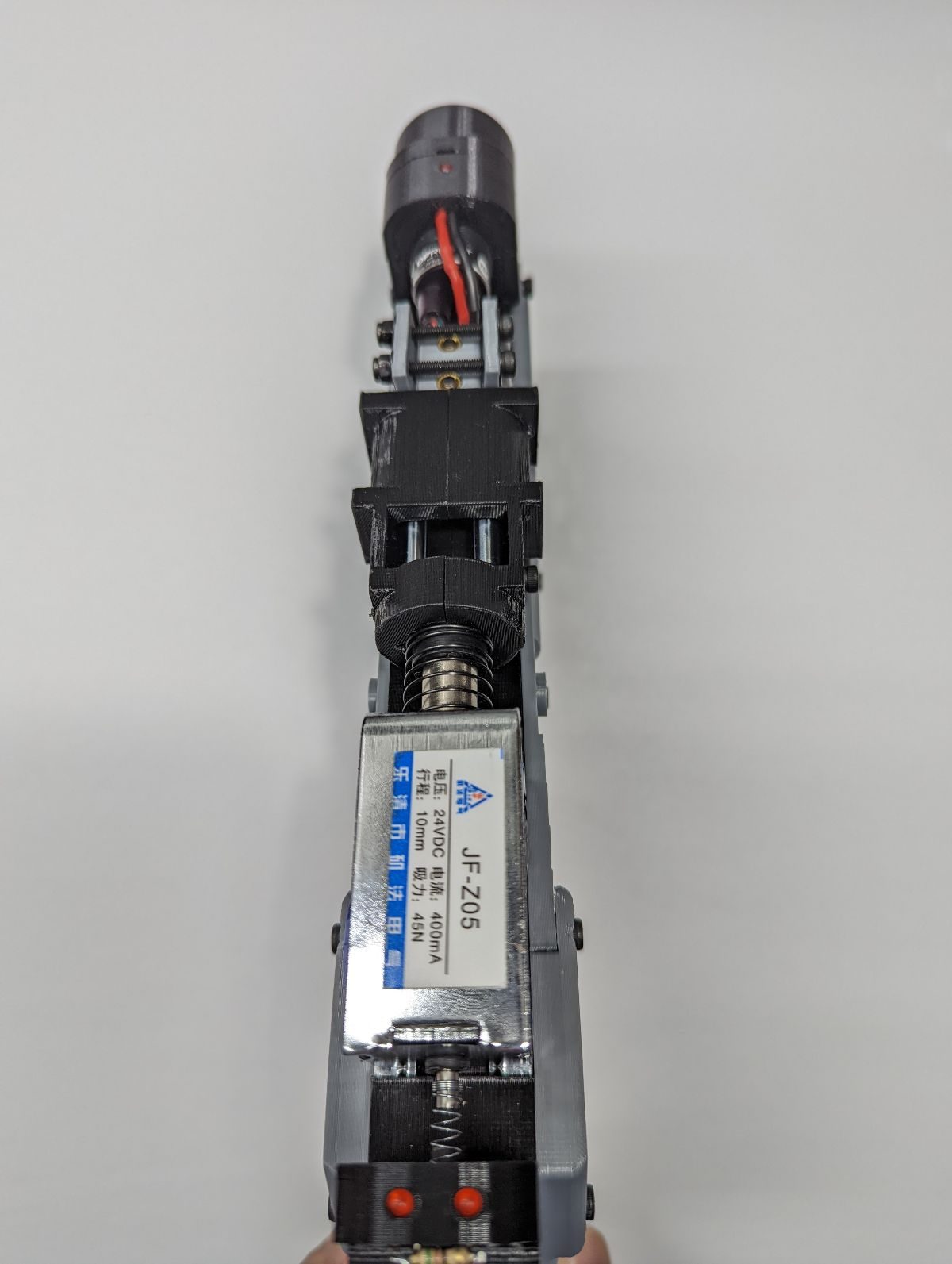
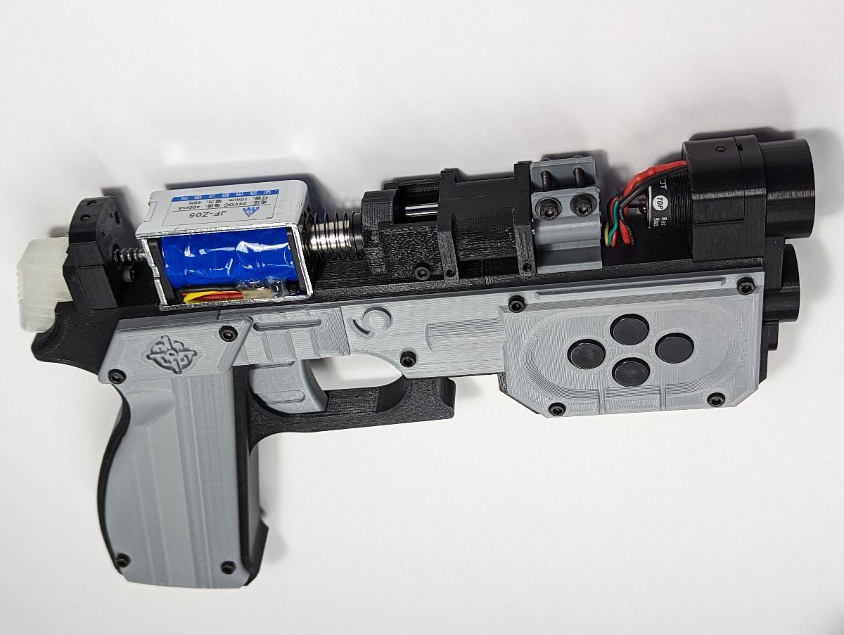
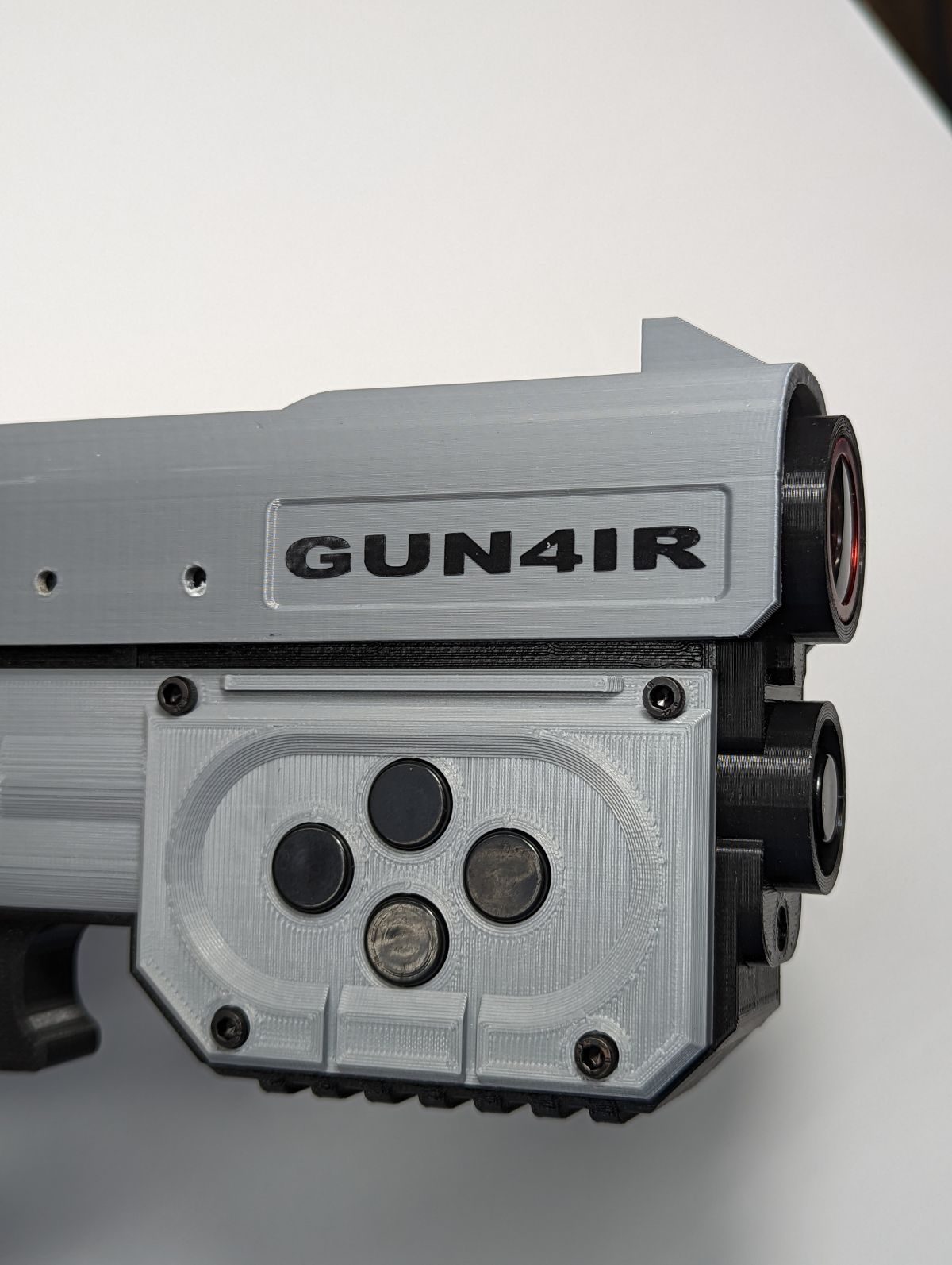
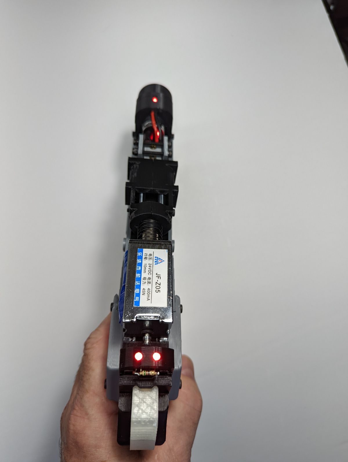
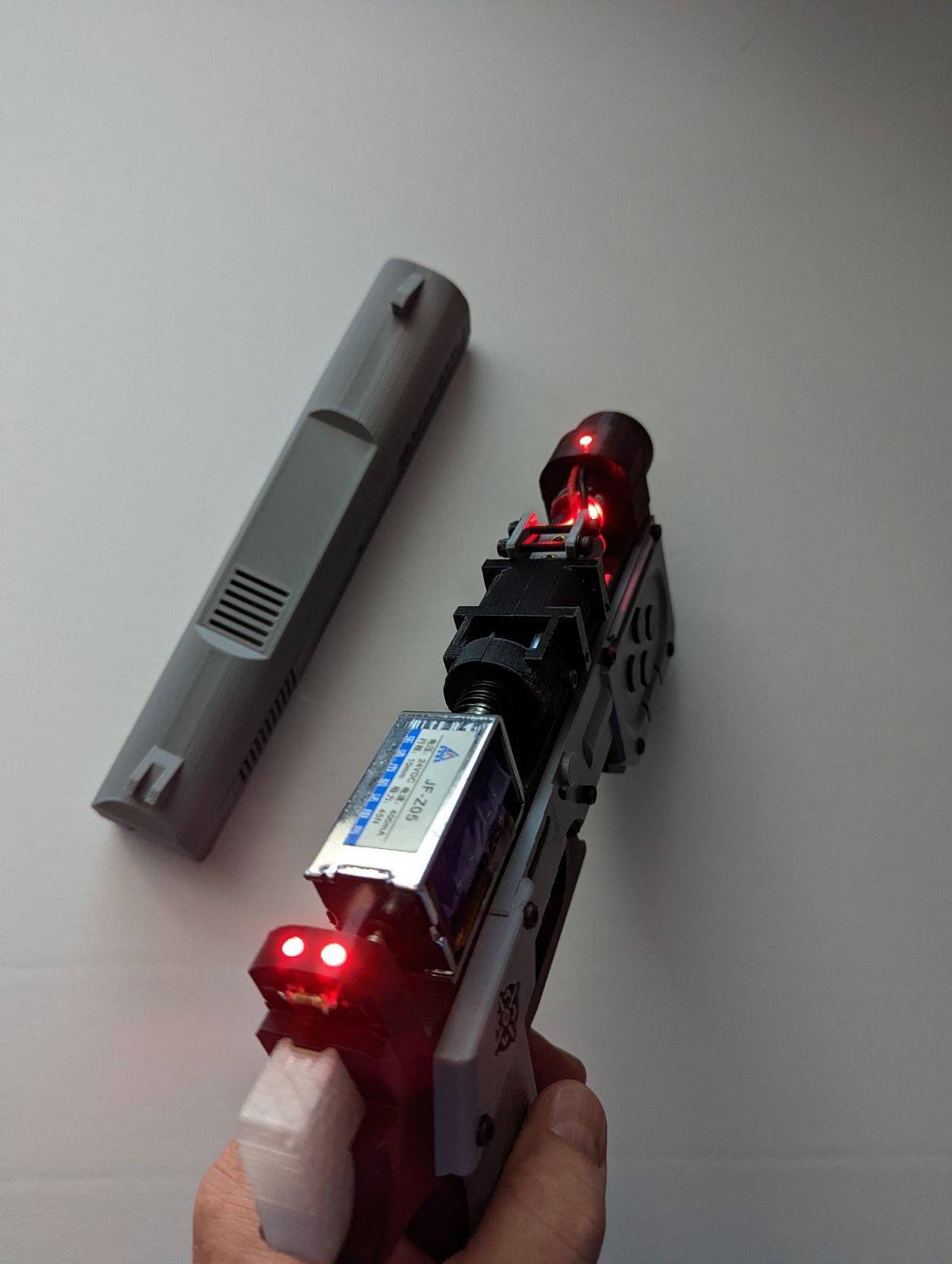
Based on the ODCON1 created by Discord user Odwalla with additional inspiration from SamRevolt and many others. Modifications include a sliding trigger rather than a hinged trigger to give more space inside the gun frame for wires & electronics. The solenoid is now mounted to the frame with screws. The sliding mechanism uses round linear bearings that slide on dual hardened steel shafts. Also has illuminated sights for more accurate pew-pewing, an RGB illuminated thumb rest. The iCON name comes from being “illuminated”.

The iCON2 uses a flat linear bearing rather than the round bearings used in the iCON1 making the build process much easier. Consider using the 3d parts from the iCON2 instead of the slide and bearing clamp parts of the iCON1.

The author marked this model as their own original creation.
This work is licensed under a CC BY-NC-SA Creative Commons (4.0 International License)

Say thanks by giving iCON a tip! Why?

25 parts have been uploaded for the iCON1, some may be alternative versions of the same part.
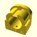
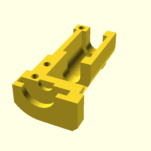
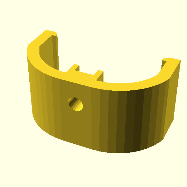
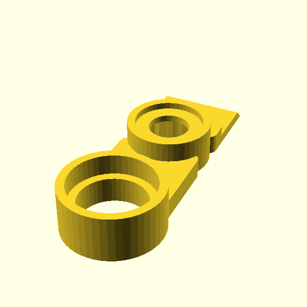
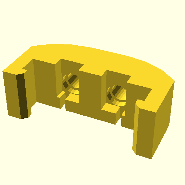
Bearing Clamp Left
rev.1 by iCON on 06 Feb 2024
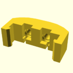
Print as shown in the STL file to prevent supports and overhangs from interfering with the fit of the bearing and the solenoid.

Suggested settings:
  • Print as shown in the STL file
  • Use normal support touching the build plate
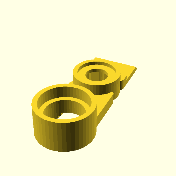
Bearing Clamp Right
rev.2 by iCON on 06 Feb 2024
Print as shown in the STL file to prevent supports and overhangs from interfering with the fit of the bearing and the solenoid.

Suggested settings:
  • Print as shown in the STL file
  • Use normal support touching the build plate
Camera Mount DF Robot
rev.2 by iCON on 06 Feb 2024
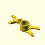
Mounts to the top front of the Front Frame using 2 M3x8 or M3x10 screws. Before mounting this part to the Front Frame, insert (2) m3x5 heat set inserts into the two larger holes in the bottom of this part. Then insert your DF Robot camera into the back side of this part and secure the position of the DF Robot camera using (1) M3x8 screw (this screw threads into the 3d print and does not use a heat set insert – DO NOT OVERTIGHTEN IT! Ignore the “TOP” label on the camera, the camera will be properly aligned when the camera cable is aligned with the “CABLE” marking on this part and the camera LED is aligned with the “LED” marking. The front of the camera should be flush with the front of this part for best results when using a fish-eye lens.

Suggested settings:
  • Print as shown in the STL file
  • Support is not required
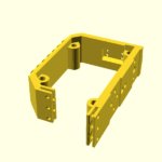
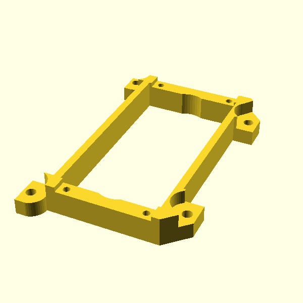
Front Frame
rev.2 by iCON on 06 Feb 2024
Suggested settings:
  • Print as shown in the STL file
  • Use normal support everywhere
Front Hardware Mount
rev.2 by iCON on 06 Feb 2024
Suggested settings:
  • Print as shown in the STL file
  • Support is not required
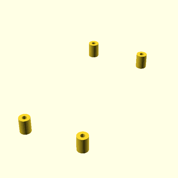
Front Hardware Spacers
rev.1 by iCON on 06 Feb 2024
Suggested settings:
  • Print as shown in the STL file
  • Support is not required
Front Side Left
rev.1 by iCON on 06 Feb 2024
Suggested settings:
  • Print as shown in the STL file
  • Support is not required
Front Side Right
rev.1 by iCON on 06 Feb 2024
Suggested settings:
  • Print as shown in the STL file
  • Support is not required
Front Sight LED Clamp
rev.1 by iCON on 06 Feb 2024
Suggested settings:
  • Print as shown in the STL file
  • Support is not required
Hammer / Thumb Rest
rev.2 by iCON on 06 Feb 2024
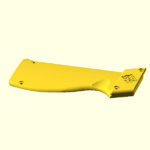
Use clear filament if you will be using an RGB LED to illuminate the the thumb rest.

Suggested settings:
  • Print as shown in the STL file
  • Support is not required
Lens Mount no IR filter
rev.2 by iCON on 06 Feb 2024
rev2: increased button hole diameter

Suggested settings:
  • Print as shown in the STL file
  • Use normal support touching the build plate
Lens Mount with IR filter
rev.1 by iCON on 06 Feb 2024
This version has an opening in the back that allows an infrared filter from a Wii remote to be press fit or glued in place between the fish-eye lens and the Wii camera module.

Suggested settings:
  • Print as shown in the STL file
Rail Mount
rev.1 by iCON on 06 Feb 2024
Suggested settings:
  • Print as shown in the STL file
  • Use normal support touching the build plate
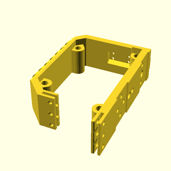
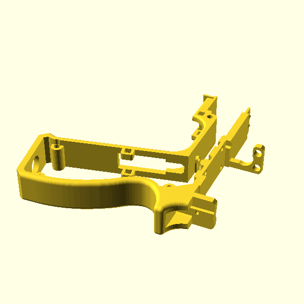
Rear Frame
rev.1 by iCON on 06 Feb 2024
Use your slicer’s support blocker to not add support to frame holes near the tongue-and-groove glue joints.

Suggested settings:
  • Print as shown in the STL file
  • Use 15% infill
  • Use normal support everywhere
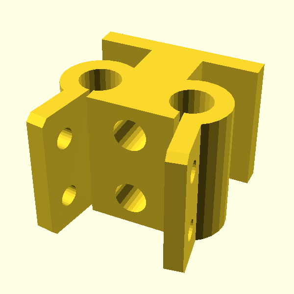
Rear Hardware Mount
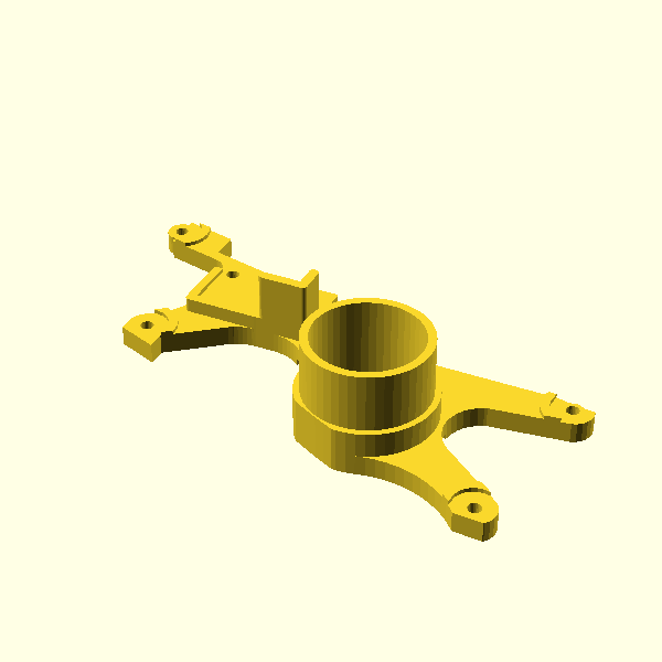
rev.2 by iCON on 06 Feb 2024
Suggested settings:
  • Print as shown in the STL file
  • Use normal support touching the build plate
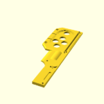
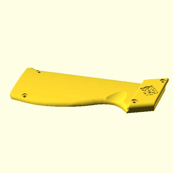
Rear Side Left
rev.1 by iCON on 06 Feb 2024
For a smoother print, this part can be printed vertically. This is the original model released by discord user Odwalla.

Suggested settings:
  • Print as shown in the STL file
  • Support is not required
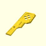
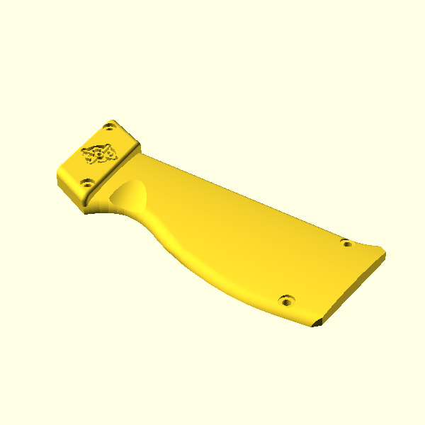
Rear Side Right
rev.1 by iCON on 06 Feb 2024
For a smoother print, this part can be printed vertically. This is the original model released by discord user Odwalla.

Suggested settings:
  • Print as shown in the STL file
  • Support is not required
Rear Sight LED Clamp
rev.1 by iCON on 06 Feb 2024
Suggested settings:
  • Print as shown in the STL file
  • Use normal support everywhere
Rear Sight LED Mount
rev.1 by iCON on 06 Feb 2024
Suggested settings:
  • Print as shown in the STL file
  • Use normal support everywhere
Slide
rev.1 by iCON on 06 Feb 2024
Suggested settings:
  • Print as shown in the STL file
  • Use tree support
Solenoid Tool
rev.1 by iCON on 06 Feb 2024
This part is used to hold the solenoid spring back while installing the left and right Bearing Clamps around the bearings and solenoid.

Suggested settings:
  • Print as shown in the STL file
  • Support is not required
Trigger for 19mm springs
rev.1 by iCON on 06 Feb 2024
Contact the author if you need a trigger for a different spring length. Use clear filament if you will be using an LED to illuminate the the trigger, and a grid infill pattern will allow light to pass through the trigger better than other infill patterns.

Suggested settings:
  • Print as shown in the STL file
  • Use 15% infill
  • Support is not required
Trigger Guard
rev.1 by iCON on 06 Feb 2024
Suggested settings:
  • Print as shown in the STL file
  • Use normal support everywhere
Trigger Guard Pins
rev.1 by iCON on 06 Feb 2024
After installing the Trigger Guard, press these to pins through the squares in the rear frame, through the trigger guard and finally through the other side of the Rear Frame. You may want to test fit the pins before installing them, some filing/sanding of the pins may be necessary to prevent the pins from getting stuck.

Suggested settings:
  • Print as shown in the STL file
  • Support is not required
Trigger Switch Guard
rev.1 by iCON on 06 Feb 2024
Keeps wires from interfering with trigger operation

Suggested settings:
  • Print as shown in the STL file
  • Support is not required
Download a printable list of parts
Heat Set Insert: M3x6x5
Quantity: 1 (Required)


Screw: M3x12mm hex or button head
Quantity: 18 (Required)

Holds side panels to frame


Screw: M3x20mm hex or button head
Quantity: 2 (Required)

Holds trigger microswitch to Rear Hardware Mount

No Purchase Links Found
LED: 3mm
Quantity: 3 (Optional)

Mounts below front and rear sights, held in place using 3d printed clamps. Resistors must be added to limit the current to no more than 20mA each. Use the Resistor Calculator website to determine the proper resistors for the color LEDs you will be using.


Microcontroller: 16MHz, 5V
Part Number: ItsyBitsy
Quantity: 1 (Required)

The ItsyBitsy is half the cost of the Arduino Micro and will allow you to build a lightgun with d-pad buttons and RGB. Genuine Teensy 2.0 boards are all but extinct although knock-off Teensy 2.0 boards are still available.

Adafruit (US)

Pimeroni (UK)
Microswitch: Arcade style
Part Number: D44X
Quantity: 1 (Required)

Trigger button. The 75g Cherry D44X is recommended but any standard size arcade microswitch will suffice. The microswitch lever (if any) must be removed before installing.

t-molding.com (US)
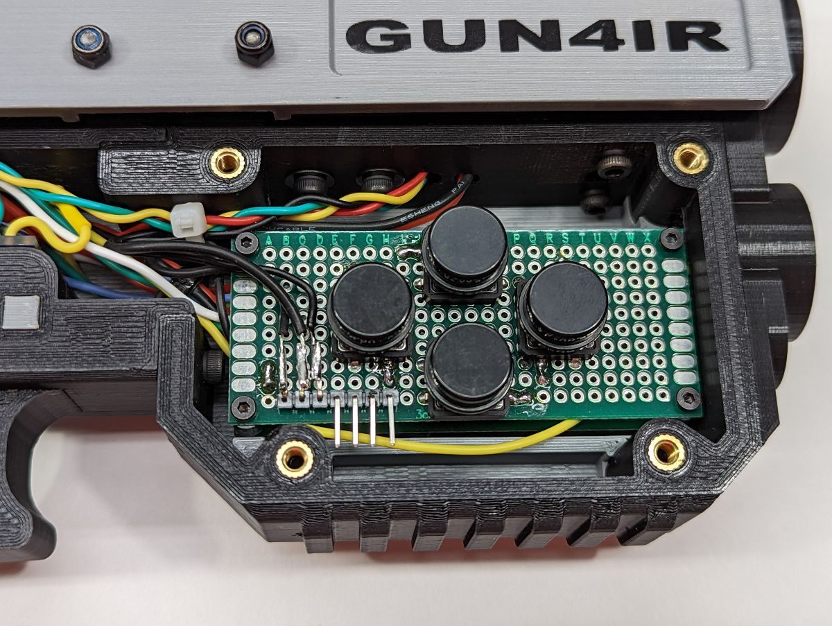
Pushbuttons: 12x12mm
Quantity: 10 (Optional)

Used for mode, up, down, left, right, A, B, start, select buttons.

Aliexpress (China/Europa)

RGB LED: 5mm Common Cathode
Quantity: 1 (Optional)

Mounts inside thumb rest using a zip-tie. Common anode RGB LEDs will not work in this build.


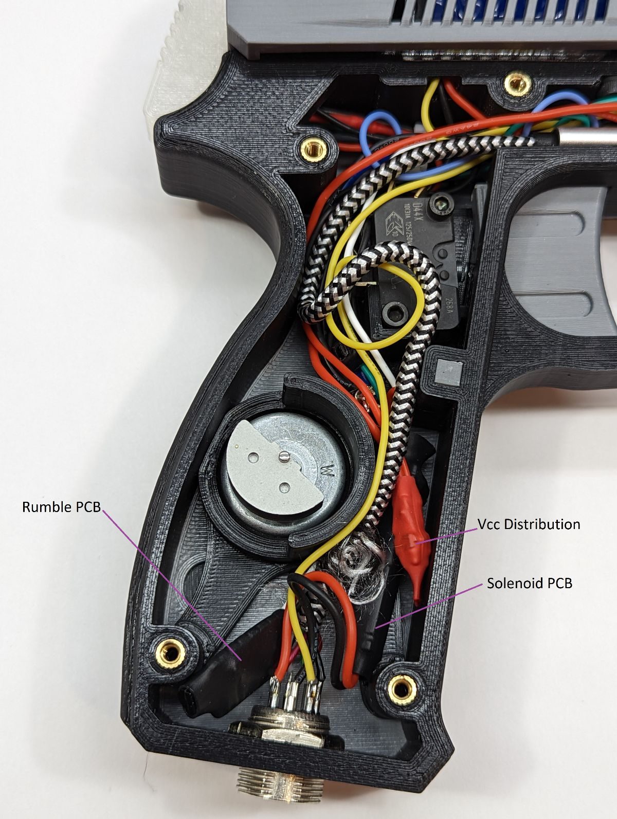
Rumble Motor: Xbox 360
Quantity: 1 (Optional)

Package contains two rumble motors each with different weight.

AliExpress (China)

Solenoid: 24VDC
Part Number: JF-Z05
Quantity: 1 (Required)

Mounts to the top of the Rear Frame using (4) M4x6mm screws.


Temperature Sensor
Part Number: TMP36
Quantity: 1 (Optional)

Used to reduce power to the solenoid if it heats up too much to prevent damage to the solenoid


Connector: 8-pin GX16 Aviation
Quantity: 1 (Required)

Mounts to the bottom of the Rear Frame. Package contains 10 pairs of male and female connectors. You could use GX16 connectors with fewer pins if you prefer If you are planning to build cables for lightguns that will use different voltage solenoids (e.g. 12VDC in one lightgun and 24VDC in another), using 8 pin connectors will prevent applying the wrong voltage to your solenoid.


Linear Ball Bearings: 6x12x19mm (IDxODxlength)
Part Number: LM6UU
Quantity: 2 (Required)

Mounts to linear motion shafts


Linear Motion Shaft: 6x62mm
Quantity: 2 (Required)

Mounts to the rail mount using (2) M3x?? screws. Shafts are not sold in the required length so they must be cut to about 61mm. Shafts are hardened steel and must be cut using special cutting tools.


Test by iCON
Updated on February 6, 2024 at 1:24 pm

Image Galleries

iCON1 images by iCONx

iCON1 Wiring by DIY Lightgun Admin

Video Galleries

No Video Galleries found

Coming soon. For now, join the DIY Lightgun discord server!

Coming soon

Coming soon
Bearing Clamp Left
Bearing Clamp Right
Camera Mount DF Robot
Front Frame
Front Hardware Mount
Front Hardware Spacers
Front Side Left
Front Side Right
Front Sight LED Clamp
Hammer / Thumb Rest
Lens Mount no IR filter
Lens Mount with IR filter
Rail Mount
Rear Frame
Rear Hardware Mount
Rear Side Left
Rear Side Right
Rear Sight LED Clamp
Rear Sight LED Mount
Slide
Solenoid Tool
Trigger for 19mm springs
Trigger Guard
Trigger Guard Pins
Trigger Switch Guard
Heat Set Insert
M3x6x5
Quantity: 1 (Required)


Screw
M3x12mm hex or button head
Quantity: 18 (Required)


Screw
M3x20mm hex or button head
Quantity: 2 (Required)

No Purchase Links Found
LED
3mm
Quantity: 3 (Optional)


Microcontroller
16MHz, 5V
P/N: ItsyBitsy
Quantity: 1 (Required)

Adafruit (US)

Pimeroni (UK)
Microswitch
Arcade style
P/N: D44X
Quantity: 1 (Required)

t-molding.com (US)
Pushbuttons
12x12mm
Quantity: 10 (Optional)

Aliexpress (China/Europa)

RGB LED
5mm Common Cathode
Quantity: 1 (Optional)


Rumble Motor
Xbox 360
Quantity: 1 (Optional)

AliExpress (China)

Solenoid
24VDC
P/N: JF-Z05
Quantity: 1 (Required)


Temperature Sensor
P/N: TMP36
Quantity: 1 (Optional)


Connector
8-pin GX16 Aviation
Quantity: 1 (Required)


Linear Ball Bearings
6x12x19mm (IDxODxlength)
P/N: LM6UU
Quantity: 2 (Required)


Linear Motion Shaft
6x62mm
Quantity: 2 (Required)


Test by iCON
Updated on February 6, 2024 at 1:24 pm

Image Galleries

iCON1 images by iCONx

iCON1 Wiring by DIY Lightgun Admin

Video Galleries

No Video Galleries found

Coming soon. For now, join the DIY Lightgun discord server!

Coming soon
Coming soon